Leaderboard


Popular Content
Showing content with the highest reputation since 12/08/2017 in Posts
-
Update: Can buy here https://www.pcmtec.com/pcmtec-editor-workshop-1-vehicle Hey Guys, Some exciting news as we tweak and adjust our product offerings. Obviously one of the power features of PCMTec for Falcons has been our CustomOS and extra features you can load into the PCM. However our licensing has been limited to get this option; you had to go to a Workshop (or buy workshop) to get this setup in your car, for the tinkerers amongst us (or engineers, or compsci students, or home-tuners) this represented a conundrum: "I want to do it myself but I have to either go to a workshop to get it done - and even then I can't change settings" -or- "I need to buy Workshop to get the features I want, and play with all the switches and dials, but its more than I need" From our perspective we saw many Professional users come across to Workshop during various promotions, only to license a single VIN. So after some internal discussion and changes with our platform we have decided to address this head on with a new product level. Our goal was to have a consistent product available for those Professional users who want Workshop features but are DIY-ers. Introducing: Falcon One Car Workshop "Basically Workshop, but limited to one VIN/PCM" What you get: Workshop Level Features - Cheaper Price Access to Workshop Level Templates (PID Controllers, all the cool workshop parameters discovered etc.) Access to the CustomOS Wizard Access to the Strategy Browser Total 10 credits included to do a single car to the top tier CustomOS What you don't get: More than one VIN/PCM can be registered to the account. (you know the whole idea behind the product) Mustang Templates and CPU Support (this is a Falcon/Territory only product) Ability to populate unlicensed files (not needed for a single car environment) Full workshop level priority support (You will need to use the guides here on the forum for configuration) Some Extra Notes: At the moment it is only an upgrade product for Professional users You still need a compatible J2534 cable to Do-It-Yourself To get the upgrade you can only have one PCM licensed on your pro account, the upgrade will be blocked otherwise. At any point you can upgrade the product for the difference to Unlimited Workshop by paying cost difference between the two. Pricing: The upgrade for professional users will be $1000(+GST), this includes 4x extra credits ($200+ Value, Brings the total 10 inc. the 6 issued from the Professional purchase). Outright will be $1600(+GST). Availability: Our plan is to make this "generally" available with the upcoming 2.1 general release. However, I would like to bring some users onboard sooner. So for Professional users that are eligible and interested, I will offer an additional discount on the purchase before this time. However I am limiting this number so we can manage this appropriately. Consider this an open pre-release invitation. These users will also receive additional support from me (and the team) initially to help them get setup etc. In addition, this will also make you eligible to the Beta program, and if you want we would bring you onboard for that and you can access the new version straight away. Gimme Gimme Gimme: Edit: It is available on the webstore at the moment outright and as an upgrade for the same price that users paid for the pre-availability period. I am unsure at this point how long the reduced pricing will last. At the moment we are not advertising the product. Thanks Everyone!10 points
-
1.25 has been released and is a maintenance release. These fixes improvements are all in the backend to help us diagnose crashes/bugs and to resolve some specific user experience issues in the custom os wizard Improved error handling that allows some errors to be "ignored" so you can save your data instead of closing the editor. Resolve a freeze in the custom operating system conversion wizard under specific use cases. Disabled the "previous" button in the custom operating system wizard as this could cause customers to reset all their tables without their knowledge. Users will have to create a new custom os using the "start over" button if they wish to create a fresh file. Minor bug fixes and improved performance. If you are experiencing any crashes or bugs that have not been addressed PLEASE file a bug report with us via the link below. If we don't know about it, it is unlikely it will be fixed. https://www.pcmtec.com/contactus In case people are wondering what we are working on, we are now working full time on version 2.xx of the Editor which we are aiming to have complete early next year. This has a massive amount of changes related to Mustang and F150 related support. Included will be all 2015-2020+ 2.3, 3.5 ecoboost and 5.0L v8 for the US, EUR and AUS Market. There are also large scale changes to the datalogging package. This will be discussed in detail when it is released.9 points
-
Hi Everyone, It's come to our attention that @2X044 was having some issues progressing and accessing these parameters because they were not available outside of the Workshop Edition. The staff here at PCMTec HQ is impressed with the progress so far and to keep this project moving and assist in bringing this idea and product to market we have upgraded @2X044's PCMTec account to One Car Workshop. We are happy to support the work they are doing and the possibility of bringing something really useful to the community. Keep up the good work!8 points
-
We are happy to announce we are finally into version 1.xx and have removed the Beta title! This is thanks to our QA team (Andrei) who has spent the past few months going through the software finding as many bugs and usability issues as possible. Version 1.11 brings the following new features. User Configurable Units After many requests we have now implemented dynamic units which will now let you use metric units instead of imperial! This is thanks to Scott who has spent the past two months implementing this feature. When opening a 2D table you will see the following new options available in the right click context menu. X axis - Units Y axis - Units Z - Units In the case of desired boost we have changed the Z units from inHg to psi Scalars can now be changed via their appropriate dropdown menu items. Here we have changed the injector slopes from their default of lb/s to lb/hr We also now have the ability to bulk change all units. Eg you can change the units of all temperature scalars and tables from °F to °C by utilising the new bulk change units drop down menu. Paste Special We have now added an excel like Paste Special menu to the right click context menu. This allows add, subtract, multiple, multiply by % and Y-Axis inversion (for those of you who can't get away from using other products!). Multiply by % does the following. Lets say you datalog LTFT and end up with the following errors By using the "multiply by %" when you paste, it will multiply the cells by the equivalent percentage. Eg add 1% for the top left cell and subtract 3% for the middle cells. Performance The performance of opening 2D views has been massively improved this release. You should see a 200-300% improvement in loading speed now. Stock File Downloads We have fixed the stock file download blocking opening and licensing of a file until the download has finished. On slow connections this could often block the user for several minutes. Now this is done in the background so that if you have a slow internet connection you can still continue tuning. Datalogging Whilst not available in this release we have made a large amount of progress with the datalogger thanks to our new staff member Matt. He has been busy adding USB analog input support to allow widebands and any other analog input to be datalogged. We have decided to skip the initial release of the datalogger and hold off until we have analog input support hence the delay in releasing the datalogging software. We are using the following USB analog input cable (8 analog inputs) which has been proven in the field with the Nistune (Nissan Tuning) software. The product is approximately $40 delivered (next delay delivery in Australia) which makes it an excellent cost effective analog input module. http://www.dlpdesign.com/usb/io8.php Other Improvements: Improved licensing popup message when a custom OS was enabled. This makes it clear you are paying for the Custom OS only and not being charged to license the entire vehicle again. Removed the VIN from the licensing model. Licensing is now locked to OSID and PCM Serial only now. This allows you to correct invalid or wrong VINs without having to contact support now. Silent save (of change history and partial write information) no longer updates the file date stamp, this means sorting by date now accurately shows when you last changed a file. BA Partial write now works on all flash types (some early BAs use a different internal flash chip). The licensing model has been modified to only use the Serial and Operating System ID. Previously we also used the VIN. This means you are now free to change the VIN of the vehicle without relicensing. Added "Upload currently open file" option to the help menu to allow you to easily upload the currently open tune to support. Any tunes uploaded will only be used for providing support and will remain the IP of the original user. If requested we will delete the tune from our server after providing support. Bug Fixes: Blocked user from "Exporting all changes to parameter file" when there was no stock file to compare with. This sometimes resulted in users producing parameter files with unexpected values due to there being no baseline history to compare to. Editor would crash if you changed the theme whilst a large scalar list was visible under certain conditions. Fixed rare crash when opening and saving files on certain PC configurations. Fixed the editor exiting immediately after open on some rare PC configurations. Strategy search inside of "Strategy List" would hide all filtered results, it now simply highlights them instead. Disabled the ability to perform a partial compare if either file is lacking stock file history to compare against. In the cases where one file was lacking stock history this would show strange compare results. Pasting VIN numbers into the VIN field now works correctly. Enabling custom os on a TEC file that had been previously tuner locked would remove the tuner lock. Tuner lock is now automatically added back. If you attempting to overwrite a tuner locked PCM with a stock file an error occured "You cannot merge the VIN from a tuner locked file". This is now resolved. Fixed a stock file download bug which in rare circumstances would get stuck in a loop downloading files over and over. Fixed an SSL certificate mis match warning which occured due to our hosting provider issuing a new certificate. Fixed several deadlocks that could occur locking the UI from being used. Fixed several unhandled exceptions which could occur.


 8 points
 -
Almost done.

 8 points
 -
If you wish to trim individual cylinders due to one cylinder running hotter than the other there are two global fuel and spark modifiers you can change. auF12418 "Calibration adders to spark angle for development and testing purposes" This value will be added to the final spark value per cylinder. Eg to remove 1 degree of timing from cylinder 6 you would change this table to the following: auF10362 "Fuel modifier per cylinder" This is a simple multiplier for the commanded fuel mass. Eg to run one cylinder 5% leaner you would modify the table by the following amount.

 7 points
 -
Assuming that the car is running those timing numbers as the actual final timing and it is following that lambda... That 98 tune looks ok, it might have too much timing from 4500 up but maybe not. Before it comes on boost, before 2250, you might be able to get more timing into it, perhaps 2 or 3 degrees. You'd wanna verify with knock ears, I use tuner nerd. 8 degrees for 18psi is a good starting point with a cold intercooler. Leave the iat spark correction stock and it'll do it's job when it heats up. The fuel looks good too. On E85 you can run more timing than you have there. It will make power the whole way up to 20 degrees but DO NOT put that much into a stock motor. I would add 4 degrees the whole way up to 4000rpm, for a max of 17 degrees, then carry that number out to redline. I would lean it out a bit as you can run E85 leaner than 98. Make it the same as your 98 tune or even 0.1 leaner. You could let it drop straight to 17 degrees after it comes on boost if you felt like it. If you have load in your log you can cross reference load and rpm to see exactly where the tune goes through the map. Tuner nerd records boost, rpm, afr and knock noise so that will also show you where it knocks, if at all. It comes with headphones too so you use them first then use the software to pinpoint it. Fyi you can run an engine very lean and it'll be fine, but letting it knock will hurt it. Don't run it lean all the time but having it go lean while tuning is fine, providing it doesn't knock from too much timing. Cylinder heat reduces resistance to knock so there is a correlation there. At the above mentioned timing figures it will not knock on E85, even if your factory knock sensor is recording noise. I turn the knock sensors off for E85 but generally leave them on for 98. It's worth a mention that boost spikes from a gear change in an auto car on 98, can and will cause knock if it isn't addressed. Anyhow there's a bit of info, it's what I would do for road tuning. I have a reasonable amount of dyno experience having done some 150 runs on my home built and self tuned 711awkw territory, as well as many other customer cars. You will find a bit more power on the dyno but that info will get you 95% of it. No need to run a stock motor too hard anyway. Final bit of advice for this post, keep your wideband where you can see it and periodically check that the fuel is there at wot. A blocked fuel filter, blocked injector baskets or failing fuel pump will lean it out.7 points
-
Here are some early screenshots showing the Datalogger version 2. This has map tracing, histograms/scatterplot and a new revamped UI. Here is an example showing a line trace over a spark multiplier map with a histogram showing min/max/avg spark values below. You can instantly create the histogram with axis pulled from a table by simply highlighting a section of the log and clicking add map trace. Here is a screenshot of the new UI which will show min/max/avg on the left hand side of the selected area. There is also a new scroll bar which shows the rpm trace making it easy to find you WOT run after a dyno trace. There will be more updates to come but this should be available around Christmas time. Thanks to @Matt for working very hard on this recently. When it is complete and ready for public testing we will put a video up.

 7 points
 -
Data logger development is back underway. We now have dynamic logging where you can select/deselect channels in the middle of a log. The video is mainly to demonstrate the mouse pan/zoom features which does away with the need for a manual axis setup which can be very time consuming to set up. The layout will still be changed quite a bit. Ultimately we will be aiming for a layout similar to the mockup below with 4 main charts each with 4 (standard) or up to 8 traces per chart. The current value and label will be shown on the side. There will also be a grid view with all active scalar values, this will mainly be for logging text values (torque sources) etc and you don't require a graph view.7 points
-
FYI Datalogging is close to release now. Keep an eye on the forums and the facebook page for updates.7 points
-
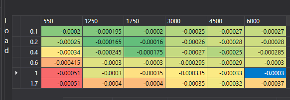
From the factory the Ford Falcon utilises a fairly aggressive throttle cut traction control. This is great for when your grandparents are driving in the rain with standard power. With 300rwkw+ this becomes quite useless and most people turn it off as it allows lots of wheel spin, then kicks in shutting the throttle completely which doesn't make for a predictable or fast car. What is not commonly known is the standard traction control system isn't just a throttle cut, it uses enleanment (or enrichment if you modify it), spark retard and throttle cut. For a performance application we can set up the standard system to simply utilise an aggressive spark retard only. This is very fast acting meaning traction loss is caught quickly, and with the throttle remaining 100% open, you do not lose boost. When coupled with boost by gear and flatshifting, this can mean putting 400rwkw to the ground with street tyres and 100% throttle is possible. It is an absolute must for a fast car. To enable an aggressive spark retard only style traction control system, we will use a lot of the tables discussed in the launch control thread which can be found here. https://forum.pcmtec.com/index.php?/topic/104-howto-bf-manual-launch-control-flat-shifting-and-torque-requesters explained/ There are two guides here, a detail one which describes what each table does and why you modify it. At the end of the thread there is a monkey procedure if you just want to get it happening asap. First we must disable the throttle cut on traction control. We do this by modifying auF0265 and setting "traction control" to 2000. This means the PCM cannot request less than 2000 ft*lb of torque during a traction control event. Eg it is disabled. Secondly we completely disable the ETC cut on traction control by setting the RPM enable setpoint ( auF0264 ) to 10,000 rpm. Technically either of these two settings would do, but to make it clear we disable both. auF0410 ETC Traction Control - Set this to disabled. On FGs there is another function auF11982 "Min torque ratio that can be achieve via spark retard to prevent backfires". Set all the torque ratios above 100°F to 0. Otherwise spark retard will be clipped at 0.3 or higher. Next there are two options, run enleanment during spark retard, or run commanded lambda. From the factory the vehicle will command 1.05 lambda. If you wish you can change this to cause an enrichment instead (safer) by setting auF1479 to something very rich like 0.5 This will mean the vehicle runs 0.5 lambda during a traction control event further reducing power. Or we can disable enleanment/enrichment during traction control entirely by modifying auF0261 and changing the traction control row to 0. This means enleanment/enrichment cannot be used during traction control. In this scenario the vehicle will run the commanded lambda instead. Finally we set the minimum requested torque ratio for spark control auF0262. This controls how aggressive the spark retard will be. Setting it to 0 means the PCM can request 0 ft*lb of torque during a traction control event. This means the PCM will use the maximum spark retard possible which will most likely hit the factory spark minimum clip of -15 degrees. Setting it this low can be too aggressive , personally in a manual vehicle I found a setting of 0.25 to be perfect as it let the vehicle maintain a very small amount of wheel spin. Next we can modify the spark retard transfer function auF2233 (BF only). By setting the very minimum settings to -70 degrees, this means the PCM will very quickly hit the minimum clip. This will affect how fast the PCM reacts to the traction control event, think of it like adjusting the proportional gain. NOTE this table is used for ALL torque based spark retard requestors. If you have an automatic vehicle and you set anything above 0.5 (the default minimum torque ratio during a gearshift) to a lower number you would also affect the minimum spark commanded during a gear shift, this could make your shifts laggy and may be completely unnecessary, for this reason it is only recommended to adjust the 0 and 0.25 cells. Finally auF16586 "Spark Min Clip" can be adjusted below the factory setting of -15 degrees. Note that going as low as -25 will induce backfires and high EGTs, only do this if you are sure your vehicle can handle the high exhaust temperatures. Sitting at -25 degrees timing for an extended period of time can burn valves very quickly and also destroy catalytic converters. Monkey guide: Set auF0265 traction control row to 2000 Set auF0264 traction control row to 10000 Set auF1479 to 0.8 lambda (for safety) Set auF0262 traction control row to 0 to 0.25 depending on how aggressive you want it. 0 is more aggressive. Set auF11982 (FG Only) to 0 for all temperatures above 100°F FG UPDATE The FG uses a much more complicated 3D model instead of auF2233. In the FG the spark delta commanded is calculated using the following equation which is derived from what I imagine is an auto generated mathematical model: Torque_ratio_commanded = 0.8 (eg we are asking for a 20% reduction in torque via spark retard) K = auF1256(rpm,load) K = -0.00032 (4500 rpm and 1.7 load in HAER1UB) Torque_ratio_commanded = 0.8; Spark_Delta = -Math.Sqrt(-(4 * K * (1 - Torque_ratio_commanded))) / (2 * K); Spark_Delta = 25 degrees Knowing this you can see that if you want more torque reduction, you need to reduce K Eg a value of K = - 0.00016 would result in 35 degrees of spark retard. A value of K = -0.00064 = 17 degrees of spark retard. So if we wanted to achieve the same outcome in an FG we would multiply the spark retard table on full load by say -0.5 Here is the original auF1256 table in an FG Here is the new table with approximately 25% more spark retard (will request approximately -35 degrees of spark retard instead of -25 degrees)


 6 points
 -
Here is the 1st to 2nd and 2nd to first shifts pressures explained. From here you should be able to work out the rest of the gears. To speed up the shift time you increase the shift pressure. You would normally only change the disengage (also know as off going) pressure if a gearbox has been build poorly and has trouble disengaging the gears. This guide is a draft, please do not take it as a gospel. UPSHIFT ZF00567 Shift pressure 12 Pressure applied to 1st gear clutch to disengage 1st gear on upshift ZF00603 Shift pressure tables 12 Pressure applied to 2nd gear clutch to engage 2nd gear on upshift ZF00623 Shift pressure tables 12 "Pressure applied to 2nd gear clutch to engage 2nd gear on upshift in performance mode Shift Pressure offset 12 ZF01446 This is an offset to the pressure based on temperature. Eg if you want to firm up shifts at certain temperatures you would increase this pressure. DOWNSHIFT ZF00605 Shift pressure tables 21 "Pressure applied to 1st gear clutch to engage 1st gear on downshift" ZF00569 Shift pressure off-going clutch 21 "Pressure applied to 2nd gear clutch to disengage 2nd gear on downshift" ZF00633 Shift Pressure 21 Pressure applied to 2nd gear clutch to disengage 2nd gear on downshift in performance mode Here is a tree diagram (we are looking to add this into the editor to simplify things) which may help explain which tables do what Line Pressure ZF00739 Line Pressure 1st gear This is the pressure applied once in gear to keep it in gear. If the gearbox is flaring or slipping (you can log the transmission slip %) then you would increase this pressure. Note that you can very quickly destroy a gearbox by changing these pressures too high or too low. Be careful. edit: Where you see "reduced downshift" or "reduced upshift" this is apparently performance mode shifting (I do not have a ZF to confirm this on). Looking at the increased shift pressures in these maps this makes sense. Update: This is as good a place as any. To increase the ZF rev limit changed the two following scalars ZF02463: Engine Speed threshold for NMOT monitoring ZF04094: Upper turbine speed threshold
 6 points
 -
Hey Guys, As I go through renaming and brushing up my technical German, here are the parameters that are particularly related to "Fußpunktadaption" (e.g. base adaptation). Temperature: Upper - ZF00026 Lower - ZF00027 Current - (Fuß > Base) - so Base current, TID: 001022 Upper - ZF00326 Lower - ZF00327 ZF01002 - Adaptable Base Current Torque: Upper - ZF02213 Lower - ZF02214 TCC/Turbine Speed: Upper - ZF02441 Lower - ZF02442 RPM: ZF03892 - Maximum permissible control deviation Time parameters of interest: ZF03229 - Time in which to adapt (possible drive time, or limit of running adaption) ZF03230 - Preparation time for soothing (possible hysteresis or settling time) ZF03231 - Time for switching on the switch point (possible drive time?) ZF03113 - Load free must be passed (possible timer for an idle time before/after adaption) TID of interest: TID002456 - Status value of the base point adaptation (so maybe a status flag of adapted/not adapted) TID000916 - Flag of the setpoint being applied (I think this might be a flag for "adaption in progress") TID002212 - Adaption Time Counter (possible relation to the timers above) TID002481 - counter adaptations (possible number of adaptation cycles performed) TID002482 - counter TCC activations For guys playing around with this, might be worth having a look at some of these TIDs and see if we can gleam anything.6 points
-
NOTE - This requires the "workshop edition" or "one car workshop edition" of the software to utilise the strategy browser. Problem: You have a vehicle where the ZF transmission calibration is not in the stock database and you do not have a stock read. Problem: You want to find the 'latest' release of a calibration for a given model of vehicle. Eg where Ford fixed various tuning issues (shift maps, air conditioner, improved idle stability etc). Wrong Solution: Pick a random strategy from a similar vehicle you recently tuned and flash it in. If you use any random operating system or strategy, the vehicle may go into a limp mode due to an ABS mismatch, or the gear ratios and shift patterns may be incorrect. There may also be a different set of system switches configured making the vehicle throw various DTCs, or certain functionality does not work correctly. Correct Solution: Use the strategy list to find a matching strategy from the same (not similar, but the same) model of vehicle. The main parameters that determine if a vehicle is the same model are the following: Axle/Trans configuration (AWD, Sedan, Ute etc) Tyre rev/mph (Tyre size - This ensures its the same level trim vehicle) TCM Calibration Level (only applicable for ZF Automatics - This specifies the matching ZF calibration shift strategy) Diff Ratio (Diff ratio changes between auto/manuals and can also change in some other models) Turbo Logic (Turbo or Super Charged model) Engine Capacity (different motor) Injector slopes (indicates injector change and hence also likely a turbo change) Average max load spark (indicates a compression or turbo change, a good example is the 2V and 3V 5.4L v8s) PCM Module Type (IO configuration of the PCM itself) Providing these numbers match you can be confident you have found the same model of vehicle. To assist this we first find the original strategy or base strategy that is currently in the vehicle via the strategy browser. First open the strategy list via Calibration Tools -> Show Falcon Calibration List We have chosen B8BG as our example as it is an automatic vehicle however we lack the stock TCM strategy in our database. Returning this vehicle to stock is difficult if the TCM has been replaced (eg you do not have the original read) hence we need to upgrade to the latest calibration. First right click on any of the columns and select Filter Editor We have only added 3 items to filter on in this example. However you can make the filter as broad or specific as you require. You may be doing a turbo conversion for example, so it is expected that many of these numbers may not line up. In this example however we expect that all numbers match. B8BJ can easily be seen to be a good match for this vehicle. The release date is a few months later in the same year, the TCM stock file is present and all other fields match. The next step is to compare these two strategies by right clicking on B8BG and selecting "Set Compare Strategy" Next right click on B8BJ and click Compare with B8BG Next browse the differences that Ford have made between the two calibrations to see what stands out. The first places to check are DTC controls and System Switches. We can see here in B8BG we have a MIL lamp for Engine Oil Temp Sensor Low. In B8BG we have "No Error" this implies there is a difference in the oil temperature setup in this vehicle. You may wish to copy these changes back. Review any other changes that you believe may be a different feature that the later edition of the vehicle may have had installed that yours did not. Many changes may only relate to different emissions standards as the year changed and can be left alone. Use care and do not blindly copy all changes over. Once you are confident the strategy is the correct one to use we will need to make a stock file. Select Create Stock File From Strategy or Catchcode Enter the new catchcode/strategy and press "Create and Merge" Next press "Load File" and load your original read to populate the VID block, serial and VIN Finally press Save/Open File Now if the previous car/file was tuned, you may wish to compare against this file and copy any tuned changes back over. To do this press Compare/History and load your previous tuned file Press Yes to partial load so you only see your tuned changes and not all of the differences from Ford that we saw earlier. In this example we have only changed the injector slopes, so we select these parameters and press apply to copy them back over. Alternatively you can use Ctrl + A to select all. You can also use the keyboard up + down + left + right keys to navigate the changes, press space to select/deselect and item for copying. Once you've applied your changes save the file. Next we recommend scanning your vehicle for DTC codes via Forscan BEFORE flashing the file in so we know if there are any pre-existing faults. Make note if there are. Next flash the newly made file into the vehicle. Start the engine and ensure the transmission is not in limp mode (stuck in 3rd gear in a ZF). Check for any fault lights, especially the DSC/ABS lamp. Finally rescan the vehicle with Forscan and check for any new fault codes, there should be none (except potentially a pending loss of comms or emissions system not ready, these will clear after a drive cycle). Next drive the vehicle and ensure ABS and cruise control still functions. These are the first things to fail if the strategy is not valid for the ABS/BCM in the vehicle. Now you have successfully changed the strategy in your vehicle. Happy tuning!


 6 points
 -
So we had an interesting ABS issue come up recently with two sperate cars. Basically there appears to be a FG build in the wild which what I would call a "Police Special". Apart from the normal police enables, this has a very particular strategy and ABS config. 1) The engine is a 'normal' FG engine build 2) ABS is set to F6 / Force 6 - 4Pot (19-01-01) 3) Unclear if the car was fit with the larger 4-pot or not at build time. 4) Strategy is HAEDLG7 - we have only ever seen it on these "ex police" vehicles. Problem being is that this particular strategy also needed the upgrade to the HAAE4 strategy for our CustomOS. When you did this - the ABS would fault. Essentially the ABS then became aware that the car was not using a F6 Strategy (or in this case, this special police hybrid). The upgrade to a F6 strategy was off the cards due to the engine differences (engine, turbo, injectors) without a whole bunch of time spent copying parameters and giving it a run on the dyno to be sure. So how do you fix it? The first option is to reset the ABS unit to the standard XR6T variant (19-06-01), but if you are running the larger brakes (4pot or 6pot) this is not ideal because it will not be using the appropriate ABS calibration for that package, additionally this requires FORSCAN and knowledge on how to use it. Second option is to figure out how the ABS knew that the PCM was not a "F6" PCM. We knew this was being communicated from the PCM somehow, but we had yet to identify a parameter in the PCM (if any) which was identifying this difference. Well due to the excellent work of @jakka351 and some time spent comparing stock files in PCMTec, we landed on the following information: - In the engine configuration frame that is sent on CAN, along with cylinder count, displacement, also contains a "peak engine torque" value. - Some anecdotal information said that for a Ford this value was always 0x82, and for a FPV this value was always a 0x8A - Doing some in-depth compares between known F6 strategies and normal strategies as well as the information on this CAN message led us to the parameter : auF12105: "Engine peak torque for SCP". This is a development parameter, and therefore only in Workshop Edition. Current Understanding is as Follows: Essentially this parameter is "130" (0x82) on all normal strategies - be it I6, V8 or otherwise. and "138" (0x8A) on all the F6 / FPV strategies. The name and allocation in the CAN frame is a misnomer, its not actually peak torque value. (I will look at renaming this in our database in the future for clarity.) When we set this value to 138 in the normal strategy with the F6 ABS, the error was cleared and we were able to proceed with MultiTune on the car, without having to change the ABS setting back to XR6T. Why is this important? Well first off it shows us the value of some of these development parameters that we continue to explore and learn about, but more importantly, it means that if you are doing a brake upgrade on a non-FPV car, you can now run the ABS in the correct setting for that brake package and ensure you don't get any warning lights / ABS no bueno. Cheers6 points
-
Just wanted to pass on a finding. I was never seeing adaption values change. I have an external cooler installed so trans temp never makes it above 70degC. They generally sat 50-65degC. Might see 70+ on a rare day. Ultimately I would like to install the Derale thermal bypass valve and a cooler fan to maintain constant trans temps around 80degC. I do not think the wide operating temperature range that my trans runs at the moment is optimal for adaption, but I have no facts to back that up, just logic that thermal stuff generally likes to be at constant temperatures. Take that with a grain of salt. I reduced the adaption value temperature setpoint ZF00027 from 70 to 50 and now the box has adapted to the new solenoids and seals I put in. I think there is no value in reducing this value if you run the factory heat exchanger setup as your trans temps will be 80+degC. Obviously log trans temps and if they're below 70degC nearly always then I then I think this mod is for you. Hope this helps someone.6 points
-
Finally worked out what the lockup columns mean. Couple of assumptions. Steady state driving, and unlock values are lower than the values in the lock area. Case 1, unlocked, accelerating If already unlocked, the M lock column is the actual OSS speed that the converter will start to apply. Under light load it will reduce slip to 0 not long after. Under heavy load it will modulate pressure to have the TCC gradually locked up by the time the OSS gets to the value in the H column. Quite smart to look ahead like it does. Case 2, locked in 2nd, accelerating, shift to 3rd The value in the L column interacts with the previous gear. For example if the 2-3 shift is carried out at 1000 OSS and we are in second gear locked up and the value in the 3L column is 1200, the TCC will unlock after the shift to 3rd then re-lock when the 3M OSS value is hit. If the 3L column is 800 the TCC will remain locked throughout the shift. Leaning towards the conclusion that we need to have the L column matching or lower than the respective shift OSS. A bit tricky with all the shift tables. But something to keep in mind if modifying shift points, the L column in the TCC schedule may need to be adjusted as well. If this is set wrong it can cause the impression of a shift flare. The improper TCC settings will show on the log as; TCC locked, shift & partial or full unlock, immediately lock. I'm thinking out the loud, the trick with the TCC settings is getting the converter to flash up to help build boost, then when the boost is coming up, get the TCC to start its lock progression ultimately ending with it fully locked before peak torque to help make it live a little longer. This will take a combination of the lock and unlock settings to not upset the cruising areas of the TCC table so it can remain locked up for economy.6 points
-
You are gonna cook your setup running 0 degrees of timing, don't do that. On E85 at 17psi you'll find your max power is close to 18 degrees of timing but you need to verify it on the dyno. I run 18.5 degrees on E85 making a touch over 700awkw at 31psi. This is a built motor obviously. Don't go crazy with timing, you can't just add more to make more power, it doesn't work like that. It'll stop making power before it knocks but it will stress the motor a lot more if you keep adding timing. It'll chuck the rods out if you go there. Maybe go back to 12psi and start from there, as it'll pull a lot harder than it is now with the correct timing in it.6 points
-
These kind of back end tasks take up a lot of our time. So if it seems like we are sitting around with our feet up, trust us, everyone is working overtime on the following: Support Resolving the out of memory issues due to 32bit J2534 driver by adding support for a new cable (OBDX FT) Overseas support (f150, Mustang, Bronco, Explorer, Maverick etc). Special shout out to the workshops who have supported us from day one. Without you we wouldn't exist and problems like this would not get fixed. We really are indebted to you (you know who you are) hence the huge 64bit update to improve your work flow. Please don't hold back, negative or positive feedback is always welcome.5 points
-
If you have a freshly rebuilt box with extra clutch packs you will find that the car bangs into gears and is generally horrible to drive. This is as the adaptive learning has to unlearn the clutch wear. It takes approximately ~1500km of light cruising to achieve this. We believe the learning algorithm learns forward (eg learns worn clutches) much faster than it learns in reverse, this is as logically a clutch can't become "unworn" so the algorithm probably was not programmed with this in mind. To disable the long term learning algorithm set ZF03182 to 0 To reset the long term learning set this to 0, start the car and put it in gear. Turn the vehicle off then set the variable back to 1. It is reported that it takes less than 100km for the vehicle to learn the clutch wear on a standard box with 150,000kms if this is done. We have another workshop trialling this out on some new boxes shortly to give us some more feedback on how accurate the learning period is and how well this works on a high hp (800hp) build with lots of extra clutch packs. Update: This is not 100% confirmed as working on modified boxes. We have had a report that it does indeed work on a standard box however. Most likely this is as there is only a certain range it can learn as one workshop trialled this on a heavily modified box and found they still had to pull a lot of pressure out of the tune for it to stop banging into gears.5 points
-
It may be a thing to also point put that there may be many cars out there that are running the wrong ABS config for the set up they have - Using mine as an example a mk1 GS (stock config Xr8), running the GT Boss 315 strategy had only been possible by setting the ABS to GT 4 Pot brake config - Wrong for the brakes on the vehicle, meaning the ABS may not be functioning at its optimum level. I do not know if this can effect stopping distance in an hard braking condition when the ABS become active. Will post further information on how editing PCM side parameters can allow the correct ABS configuration to work with the desired strategy.5 points
-
We have been busy working on a few projects in the background (cruise control multi tunes, datalogging) with one of the projects being Mustang support. We have implemented read-write support for the Tricore TC1791 controller used in the 2015-2017 Mustangs with the new Tricore TC29x Aurix processor being worked on shortly (2017-2019). Ecoboost MDG1 processor support will come later if the demand is there. We have started mapping the Mustang and here is a sneak preview of what we will aim to offer. Partial write. This should be capable of dropping the Mustang write time from 50 seconds down to ~10-15 seconds. If we can embed the bootloader into a Custom OS this could possibly drop to a few seconds max. Access to ~11,000 parameters for the TC1791, and access to over 20,000 parameters for the TC29x direct injection 10 speed auto.5 points
-
For our internal QA we have built a simple canbus dash emulator. As the Mk2 FG uses a canbus dash this means we can emulate the cruise control buttons via canbus to do an end to end test of the multi tune system. This program doesn't use any of our source code and instead uses an open source J2534 library https://github.com/BrianHumlicek/J2534-Sharp We are also using a free version of the Arction WPF Gauge library so this program can be freely distributed. https://www.arction.com/free-gauges/ Here is a video of the emulator in action. This might be useful for anyone who is doing a mail order multi tune. You can download the program and source code here: https://pcmtecgeneralstorage.blob.core.windows.net/public/TestApps%2FPcmtec.DashEmulator.zip This includes a mk2 FG file which with PATS turned off so you can test this on the bench. BA/BF/FG Mk1 does not support canbus cruise control, so you will need to wire up the cruise control buttons manually.5 points
-
0.75 has been officially released as of Saturday 19/1/19 Please download the official non beta update from out website below: https://www.pcmtec.com/downloads If you have been using an intermediate release that we have sent you previously (even today!) please update to the version on the website as it includes some minor changes. New features: Custom Operating System Custom Operating system is now available via the editor. This means you can enable a Custom OS via a drop down menu system. You can change the following items: You can read more about how to set up the new Custom Operating System here: Tuner Lock. You can now apply and remove a tuner lock via a dropdown menu option View/Populate Unlicensed Files Workshop users now have a menu item under calibration tools called "Populate Unlicensed file". This will allow you to perform a read of a vehicle and view the contents of the file without licensing it. This requires an internet connection to work. Fix Corrupted OSID Added "Fix Corrupted OSID" to the calibration drop down menu. This is very handy when converting tunes from other products. Quick Access We now have a quick access menu which shows commonly opened parameters. This works in a similar fashion to the Windows 10 Explorer quick access menu. Custom groups will be coming soon. License Viewer You can now view all of your licenses via the license viewer which can be found under the help menu. About An about dialog is now available from the Help menu. This shows the current version and your credits. Flash Only Package (Multiple Tune Storage) officially released Unit Converter/Gear Calculator Axis Rescale/Reinterpolate Wizard Calibration List A calibration list is now available for workshops users. This lists approximately 900 calibrations and some common information about them, such as average spark values, fuel injector slopes, gear ratios and many other interesting items. BA Partial Write BA Partial Write has now been added and can write a BA PCM in approximately 22 seconds BA Flex Fuel The BA now supports flex fuel via utilising the boost sensor input. The MAP sensor is now used for boost pressure instead. Improvements Pressing "Open" on the return to stock view closes the dialog if a file is successfully opened to speed up creating a new stock file. The enter key will also validate input instead of just the OK button. Layout has also been changed slightly. Open/Import now remember the previous folder you opened. So if you typically store your parameter files in one directory and tunes in another, you won't constantly have to go back and forth between folders as it will remember the last place you were. Removed the 2D line view for Axis editing as it meant you could enter in strange cell numbers. You can now edit axis values out of sequential order, you will only be warned upon saving/opening the file. Previously this action was block which interrupted user workflow. After pressing "Export to value file" parameters are now automatically unchecked. Credit count is automatically checked each time you attempt to license a file. This means if you buy credits you no longer have to restart the editor for the credit count to be updated. Search delay for the navigator has been reduced to improve the search speed. Partial compare now compares items if the parameter in EITHER file is different to stock, not just the compare file. Increased Custom OS blend and voltage table resolution. Many Custom OS changes, eg you can now select "Import License Information" message on manual merge wizard was inconsistent. Serial was truncated on various return to stock view screens. Added flash write license information to the file information dialog. Highlighting cells on the 2d curve now map traces the cells in the table view above. Made small icons the default to increase screen real estate. Can no longer edit strategy/osid/vin of unlicensed files which would cause confusion when licensing the file. Improved tuner lock. If you use an existing file for the return to stock wizard that has a corrupted strategy it will now prompt you to fix it. 2D curve X-Axis is now linear and proportional to the units used. Columns now auto resize better. Axis with all values as 0 are now displayed better. Exporting all changed parameters to a parameter file would also export the strategy/osid/vin. This has been removed. File is now silently saved after a flash write. This means if you do not save the file after a flash write, next time you open the file partial write will work immediately. When writing a vehicles flash, you will be warned and prompted if you are sure you want to continue if windows reports less than 10 minutes of battery life left. Block PCs with extremely short hibernation timers (< 5 minutes) from sleeping the PC during a flash write. Open file performance improved by ~25% if you have a large number of licenses. Pressing save no longer collapses the navigator tree Bug Fixes If you licensed a Custom OS for 5 credits then attempted to license a non custom OS version of the same OS it would prompt you for another 2 credits. Now you are only ever charged a maximum of 5 credits for licensing a Custom OS and the original OS regardless of the order you license the files. Fixed a bug where editing an axis with units such as "inHG" in a rare scenario would not update correctly. Fixed various fatal unhandled exceptions which would close the program. Compare/Change History would show hidden/invalid/disabled parameters. Pressing and holding down the right arrow key when in the navigator could cause a crash. Fixed a rare crash if you change a parameter and immediately click the compare/history button at the same time. City would not populate within the login view. EULA would let you accept multiple times. EULA would let you reject after accepting. Fixed the EULA showing an IO Access error when downloading in some instances. Fixed the EULA displaying twice in some instances. Fixed multiple failed logins in a row on the Login panel with a small screen pushing the login/ok button off the screen. Fixed lots of flash only tablet software licensing issues. Fixed various Custom OS Axis display issues. Fixed Undo/Redo not working correctly. Fixed VIN/Strategy/OSID undo being blocked. In some cases changing multiple cells at once in the table view would ignore the changes. Fixed the scalar undo/redo buttons which did not function correctly. Fixed the return to stock wizard continuing to the next step if the download failed. Fixed an issue where you couldn't drag edit the right most point on a 2d curve. Fixed a missing horizontal scroll bar on the change history view. "Show absolute differences" was not working on the tableview. Importing a value file did not add a history point or update the change history if it was open. Mouse back and forward keys now work correctly. If you edited a value in a table then immediately pressed write without exiting the cell editor, the change would not be written to the vehicle. Now the cell is immediately validated when pressing flash write, even if the cell editor is still active. If you had unsaved changes, pressed close then press "yes" to "would you like to save your changes?" it would not necessarily always save the file. This is now fixed. Change history would occasionally jump around the screen when clicking the small arrows/triangles to expand a row. Exporting custom os triggers to a value file could cause a crash upon reimporting. These can no longer be exported.


 5 points
 -
Just thought I would give yous a little update and give you some more information on shift patterns as it may help some of yous out. After having a look at the standard ZF tune that comes in my FG F6, FG XR6T and a FG GT that I recently had a play with, it appears that Drive and Performance modes shift patterns are constant between the three of them, so if "x" shift pattern was a drive mode on the F6 it was also a drive mode on the GT & XR6T and same as performance modes. The difference I found was that shift pattern 35 through to 38 on the GT are Limp modes. The table below is shift table 35 for the GT which shows it won't allow it change down to 1st or 2nd. With the two turbo 6 cylinder shift patterns 35 through 38 still allowed the ZF to shift down to 1st and 2nd. The best way I've found to differentiate between a drive, performance, manual, limp etc mode is the characteristics of each table. For example in a limp mode the gearbox won't be able to change into certain gears and generally that's lower gears and the shift table above reflects that. If you know what the ZF will do in certain modes then you can figure out which mode is which patterns.
 5 points
 -
Hi everyone, I have thrown together a simple web application that might be useful for people working on injector scaling. As has been discussed many times on this forum, changing the low slope / breakpoint / deadtime offset affects the amount of fuel delivered at higher pulse widths. This app provides you with the ability to adjust these values with a slider to help figure out the optimal injector scaling (or at least as close to optimal as possible). The site is currently hosted at https://injectorscaling.fly.dev/ Fill in the information in the attached spreadsheet and upload it to the site to play around. Unfortunately there is a 30 second time out with fly.io (that I can’t change), so you might need to refresh your page every so often. The top plot shows you a comparison of the original injector settings (black line) and the new settings (red line) – based on the sliders of the left. The dashed horizontal lines show the breakpoint (change between low and high slopes). The vertical dashed lines show the injector minimum pulse width (which isn’t really used in this app). The second plot shows what (approximate) effects these changes will have on the amount of delivered fuel. I’m not quite happy with this part, so I’m happy to have suggestions/comments. However, you can think of this like so: the PCM asks for a certain amount of fuel and uses the first plot like a look up table (draw a line in from the y-axis until you hit the black line, then draw a line down to the x-axis to see the pulse width required). To make this plot, I then draw a line up from that pulse width until we hit the red line, then draw a line across to the y-axis. This would be the amount of fuel that is delivered (assuming all of the new values are actually correct). The difference in expected vs delivered is converted to a pseudo long-term fuel trim and shown on the graph. Note: this could also be shown for pulse width instead of fuel on the x-axis. There is another plot below those two that show the injector deadtime vs battery voltage. I allow you to change the battery voltage on the slider, but it doesn’t qualitatively change much in the first two graphs. Rather than change all the values of this, I have applied a simple “offset” that just adds or subtracts a fixed time to the injector deadtime. You can see that it raises or lowers the entire curve and can make a large difference in the first two plots. This is just a first prototype. I was hoping to have more features before releasing it, but I haven’t made much progress due to time constraints. I have another app for viewing the spark advance table under different engine conditions e.g. sliders to change ECT, ACT, Lambda, catalytic converter temp etc. The excel file has 18 tabs (not all of which are needed for all situations), so it isn’t the friendliest thing to use. I’ll post when this site is up. Injector_scaling.xlsx
 4 points
 -
UPDATE: As built data is being collected here, thanks to Mick for starting the group, great to see everyone contributing as it helps us all out. https://www.facebook.com/groups/australianforscanusersgroup Original Post: It is becoming increasingly common for customers to convert NA Falcons to Turbo. When the entire drive train and all modules are swapped this is relatively easy, the problem occurs when customers add a turbo to an NA engine swapping the PCM only, leaving the NA ABS module. Previously the advice was to source a turbo ABS module from the same vehicle, or attempt to reprogram it with Ford IDS which is fairly tricky. Recently there have been updates to Forscan which allow editing the ABS module as built data. As such you can change a non turbo ABS module to a turbo ABS module. One customer has recently tested this on a Mk1 NA FG automatic ZF 6 speed which had a turbo PCM, TCM installed but the NA ABS module was left in the car. To reprogram the ABS module we installed Forscan with an extended functionality license (Very cheap and a great product!) and saved the NA ABS module as built data as a backup. The customer then connected to a Mk1 FG Turbo ZF 6 speed and downloaded the as built data. The turbo as built data was then uploaded to the NA conversion vehicle and voila, no more ABS fault. Please be aware if this is done wrong you may be left with a non functional ABS system. Process we followed is below: Download Forscan here: https://forscan.org/download.html Then connect to the vehicle. Select Configuration and Programming and select the ABS module. Now "Save All" the as-built data. Follow the same steps on the turbo vehicle. Now "Load All" and "Write All" the as built file from the turbo vehicle on the converted NA vehicle and restore the data. If you have any issues you can always restore your backup. If you have a manual BF or an auto Mk1 FG you can use the supplied files below AT YOUR OWN RISK. Now please ensure you test these changes in a safe environment on an engine dyno if possible. Also test your ABS still functions correctly afterwards in a safe environment. There is no guarantees with this process however it appears to work on the FG Mk1 Series of vehicles which has been tested. As built data can be downloaded below: FG Mk1 ZF6 Turbo as built FG-Mk1-XR6T-ZF6_Turbo_ABS.abt FG Mk1 ZF6 NA as built FG-Mk1-NA-ZF6_ABS.abt BF Mk2 6 Speed Manual Turbo as built BF 6 Speed Manual ABS.abt Anyone who has the following and can please read and upload your as built files from your ABS modules it would be muchly appreciated. Please note the model (eg ute, sedan, g6 etc). This will greatly assist others if you can share this information. BA Manual BA Auto Turbo BF Auto Turbo FG Mk1 Manual Turbo FG Mk2 Manual Turbo FG Mk2 Auto Turbo


 4 points
 -
Hey everyone, I just came across this project and am really impressed with what you guys have managed to do with the factory PCM. I'm keen to get involved with the project once I get up to speed with it. Much more reading to go on my part yet! My day to day is dyno tuning and race care electronics, mostly with standalones, based in NZ. I'm currently looking to get a new shop project car, recently decided on a Barra and just the other day came across PCMTEC and have decided it's definitely the right platform for me! Here's my 2 cents on the current topic, hopefully it's of use to somone. I use the Honeywell MIP series for every race car we build, measuring oil, fuel and coolant pressure, with great success. But they are sensitive little things that can be prone to failure if they don't get just what they need. The datasheet is a great resource https://www.farnell.com/datasheets/2897784.pdf The big one that kills them is vibration. They don't like to be directly bolted to an engine, they are much more likely to survive when they are remote mounted with a rubber isolated mount. Haltech do a cheap remote mount kit https://www.haltech.com/product/ht-039103-pressure-sensor-extension-kit/ The other big trap is water getting into the connector causing corrosion. Right angle boots like this are a big help https://msel.co.nz/right-angle-rubber-boot-for-pressure-sensors/ The failure mode on these sensors tends to be intermittent and erratic too which is a big headache. Looking at the data you'll see numbers that don't make sense or brief spikes to 0. It's worth proceeding with caution if you're looking to cut the engine on a street car. I typically will only implement a limiter to ~1500rpm on loss of oil pressure on a street car to allow the driver to limp the car out of the path of potential danger. An emergency over ride switch or button is another option. 90% of the cuts we see are from wiring faults or sensor failures. But the other 10% has saved many race motors! Also you can get the sensors for a good price with free shipping here https://nz.element14.com/honeywell/mipan2xx100psaax/pressure-transducer-seal-gauge/dp/3364907 Octopart.com is the go to find the best place to buy anything electronic4 points
-
Put auF0220 back to stock. This table should not be zero'd out. Old literature suggested halving it but imo that is still not a good idea and doesn't work very well unless on E85. The way that tune file is set up isn't how you should go about tuning. It will be doughy to drive and have no top end pull. Leave the MBT map stock, leave all of the corrections stock, then you modify the BLK map to suit the timing curve that it outputs. If you are worried about detonation, get a set of knock ears for starters, when you start to tune it you should remove 4 degrees from the whole BLK map and start with a low boost setting, eg: 5psi.4 points
-
It's public as in you can download someone's software that they spent a lot of time on and didn't charge a cent for. Most people do this once or twice and get jaded. Don't underestimate the value of your time. If it takes you months to figure out you should charge for your time. Undercharging discourages all the other smart people out there from having a crack and innovating.4 points
-
A few people have asked about Spark so here is a brief explanation of how the ford spark is calculated. The parameter IDs are for BF. FG has more adders as well. The final commanded spark is a combination of multiple tables. This is not an exhaustive list however this is the ones you need to look at. Borderline Knock - auF16593 (this is the maximum spark before the engine will knock) MBT Spark - auF16630 (this is the maximum spark before you stop increasing torque) Coolant temp MBT adjustment - auF2433 Spark ECT Correction - auF0222 This retards timing when your coolant temp gets too hot ECT Correction Multiplier - auF0223 This is a multiplier for the above table. This table can add up to 4 degrees of spark at peak load, make sure you are aware of it. Spark IAT Correction - auF0220 This retards timing when your intake air temp gets too hot IAT Correction Multiplier - auF0221 This is a multiplier for the above table. Spark BLK table adder (lambda correction) - auF0218 - This adds or subtracts timing based on the commanded lambda. This one will catch you out, it makes quite large adjustments based on your commanded lambda, a lot of people zero out the positive numbers in this table. Steady state/cruise This is an approximation of the calculation for when driving under normal circumstances without cold start or deacceleration active. It is an esimation, at some stage we want to make a proper write up on this from exactly what is in the assembly code. This is possibly incorrect or has omissions, so please take this into account. If anyone knows more detail than this please post up any corrections. Final Spark = Math.Min(auF16593 + auF0218 + auF0223 * auF0222 + auF0220 * auF0221, auF16630-auF2433) Or Final Spark = Minimum(BLK + lambda correction + IAT Correction + ECT Correction, MBT-MBT adjustment) IDLE Now if you are at idle it uses a PID loop to control spark. Deacceleration If you are deaccelerating (eg closed throttle) it uses auF0228 (Decel Spark Angle) Cold Start If you are on cold start it uses the following: Maximum Cold Start auF0210 Maximum Cold Start Adder auF0212 Maximum Cold Start Adder #2 auF0211 Cold Start Spark = auF0210 + auF0212 + auF0211 Final Cold Start Spark Max = Math.Min(Cold Start Spark, BLK, MBT-MBT Adjustment) (eg whichever is smaller of the 3 numbers) It will then use the idle feedback algorithm to add/subtract spark to obtain a given rpm. Eg if you have a setpoint of 750rpm and your idle is 700 rpm it will add spark, if it is 800 rpm it will subtract spark. The final figure will be clipped at "Final Cold Start Spark Max" which is calculated above. There is also an "anti stall multiplier" which is added in, most of the time this does nothing unless the rpm dips very low. If you want to datalog final cold start spark max, log the following DMR spk_lold_cld Transient conditions This is when changing the rate of acceleration, eg a change in the rate of load (the derivative of load). For example accelerating slowly, then flattening the throttle. Spark Retard for Tip-In auF0233 Tip in detonation control auF1705 Final Spark Transient = Final Spark (from the above calculation) + auF0233 * auF1705 Torque Control There are various times the PCM will command torque reduction which is achieved by ignition retard and in some conditions ETC (throttle feathering/closing). This is under traction control, changing gears in an automatic etc. Spark Retard (torque ratio) auF0263 Going forward we would like to build a spark simulator. Eg you enter in RPM, Load, IAT and ECT with sliders and you can see what the final spark will likely be, for now you would need to fill out these equations in excel by hand. If you do build anything feel free to post it up, it will be very helpful for others. Why borderline and MBT? Regarding the borderline and MBT tables the reasoning is to achieve maximum timing for performance in all possible conditions. If you use an 120 octane race fuel and find the maximum torque an engine can make then log the spark, this will be your MBT (maximum brake torque) table. Then if you use 91 octane fuel (I think the US fuel is different again) and find the maximum spark the engine can take before knocking this is your borderline knock table. Then you vary the lambda and see how much extra timing the borderline table can take and this creates your lambda spark table. Now this may overlap, eg the borderline knock may be higher than maximum torque. Eg you canrun 50 degrees of timing at cruise however the vehicle will stop making more torque after about 40-45 degrees hence there is no point in running any more. The PCM takes the lowest value of these two tables for this reason. The goal of all these tables and adders is so you can run the absolute maximum timing possible at all temperatures and load. Ford have done a great job of achieving this on a stock calibration, eg the car will run on the ragged edge of knock at all times getting maximum performance and maximum fuel economy (within emissions windows) on 91 fuel. If you were to try and achieve this level of tune in the aftermarket world you would need an engine dyno cell, thousands of litres of fuel and the ability to control ECT and IAT. It would take you a long time, I've been told it takes Ford 3 calibrators 25 weeks to calibrate an engine from scratch. The issue with aftermarket tuning is you do not have the resources to hit each load cell at every single IAT and ECT combination to determine maximum torque and maximum timing. So you compromise and tune the vehicle for the worst case, this means in cold weather/transient conditions you are probably running far less timing than you actually could. Setting the upper loads of the MBT and Borderline tables to be the same figures means you are safe in that you can be guaranteed the PCM will not ever run any more timing than this. It also means at low ECT/IAT temps you will be running less timing and hence less power than is possible.4 points
-
Are you any good with a die grinder? You can use a high speed drill and a long carbide bit too. Before you go external gate you should check your turbine housing and make sure there is a good port job on it. You want a nice radius going into the wg hole and you can actually raise the roof slightly (wg hole facing up) so there is less height to the angle into it. I leave the back side of the hole square to help with wg priority. That combined with minimal preload should give you a much lower minimum boost. It takes about an hours worth of grinding to go from stock to perfect. Suffice to say, don't touch the seat or it will probably leak. I recently did this to a pulsar 3584rs with a TS 12psi actuator, decent preload and straight through 3.5 inch exhaust. I could run as low as 13psi the whole way to redline. Same turbo with untouched turbine housing on my territory with a very free flowing custom 4 inch exhaust and it would boost spike to 28psi with 0 duty. Anyhow there's some info for you and other passers by. It's what I would be doing before spending money and if it doesn't help it's only some wasted time.4 points
-
I've had a similar flare issue when shifting from 3-4 at light throttle around 2000rpm. It would only do it on the first shift from 3-4, didn't matter if it was hot or cold. I found from this guide that changing all the unlock variable in the 0-20% range to 0 in third helped the issue. https://fordforums.com.au/showpost.php?p=5195223&postcount=16 TCC table.xls4 points
-
This is more of a how do I tune, rather than a what parameter should I adjust question. Everything can be found by searching on the internet. You can also learn to tune with hp acadamy. However, I will tell you a few things to tune a na car. You need a wideband and you need knock ears for road tuning... Aim for around 13:1 afr at WOT and keep it in closed loop until about 2750rpm. Try to get 30 or so degrees of timing at WOT, 34 is great. The engine and fuel type will dictate how much timing is required. To work out how much timing you can get into it, start the WOT afr at 12:1 and gradually increase timing. When it starts to knock, pull the timing back a couple of degrees or 3 and start to lean it out. When it starts knocking again you have found a balance. Get the timing as high as you can without going too rich... on a knock limited engine... 12:1 is much too rich for an daily street na motor and is just a starting point for setting the timing. It might be happy at 12.5:1 and it might be happy at 13.5:1. The timing will tell you where the fuel is happy and vice versa, in a road tuning scenario, within reason. Make sure you use 98 octane fuel for best results. For better cruise economy there is an O2 bias offset table. Play with that so you cruise at 15.5:1. That is a general approach to na tuning with some falcon specific stuff in there, some cars will want more or less timing and fuel, but that info should get you in the ball park.4 points
-
For anyone who wants to know what it is like to write code all day. I present to you probably the best description of what it is like. https://www.stilldrinking.org/programming-sucks4 points
-
Having done a bunch of road running myself, I find the less visual distractions the better. You need to watch a wideband, although after a few tries the fuel will be safe enough. You might need to watch a boost gauge. You need to watch the temp gauge. Must importantly you need to watch the road. Rwd starts getting sketchy a little after 300rwkw and AWD starts getting sketchy after 550awkw or so, imo. Having to hold a car straight while flat out in 3rd/4th is hectic enough by itself, let alone watching gauges etc. With knock detection I use the headphones primarily, then review the subsequent knock data from tuner nerd. I've also done a bunch of dyno tuning and even then you need to watch the fuel and boost very closely when you start making big power. With headphones you will hear the onset of knock well before it detonates severely, a light may not pick it up in time when you include your reaction time to the light. Anyway just a few things to think about.4 points
-
I turn the knock detection off in the tune and plug my knock ears into the factory sensors. I found that just unplugging the knock sensors will make the tune pull the max amount of timing it can, hence why turning it off.4 points
-
Hi hjtrbo, As a bit of background on the tuner lock when you say "Most customers are very loyal to there tuner for the life of that vehicles ownership" is not our experience at all with Ford vehicles. I believe it is true for Holden cars but we see many customers shop around and get the tune done again. The issue you have sounds like it is remote tuning and that your workshop wont invest the time to do that, purely a business call by them. You could ask another tuner who is willing to do that or even leave the tune unlocked so you could do it yourself (there will be one near you). Further you can negotiate with your original tuner to get the tune sent to another tuner and we will transfer the licenses from one tuner to the other if they agree. We could facilitate this if you want. We do not unlock tuner locked cars for many reasons. There is an interesting story where the coroner/police asked us to unlock a tune and we could not without a lot of work and a court order. Much better for them to find the original tuner and negotiate with them what was done. Another fun one is that some have tried to move a flex tune to another vehicle, good time waster that one is if you like bricking vehicles I fully understand your frustration. Roland and I started PCMTec for this exact reason, I had to do 130kms across town every time I needed a tune changed and then it was only once in a few months. Fortunately my tuner said he would show me how to tune and I could purchase another product and start. This was the beginning of PCMTec for me. A multi tune is quite protected, I can take over your support ticket if you want and see what we can do.4 points
-
You can disagree with tuner lock as much as you want but if you do such a thing you'll be hurting our top customers. This isn't a hobby for them, it's their lively hood, it is what pays their bills, some of them have million dollar loans for dynos and sheds, this would mean less revenue for them and hence less revenue for us. This means less R&D funds for us to continue building cool software like the multi tune and our new datalogging package. Can I make a suggestion. If you have enough time to even consider something like this maybe put it towards learning to tune or something else with a positive outcome for the Australian tuning community.4 points
-
Hi Everyone, I'm a data scientist by trade and have been considering throwing together a script that could aid in dialing in injector slopes, breakpoint and deadtime. The input would be a reasonable size datalog of AFR, injector pulse widths and such. Using some non-linear optimization, it should be possible to identify what variables need to be changed to minimize lambda errors. It should be possible to differentiate speed density errors from injector scaling errors, as the lambda errors will track with injector pulse width. I've only just got my wideband sensor working on the bench (long story... did you know there are 720 ways to wire up a 6 wire sensor?). So I'll be doing some logging and prototyping. I'd be happy to have anybodies input on this.4 points
-
Well we all start somewhere don't we... This is a simple way of looking at it; Think of the slope numbers as how big the ecu thinks the injector is. For the sake of making it easy, lets assume both slopes are the same number. If you make them 100 the ecu will run an afr of 14.7 for example. It wont actually be that afr but lets just say it is. If we make the slope number smaller, the ecu thinks the injector is smaller and will open the injector for longer which will run richer. So there is one way of thinking about how the size of the slopes work. The reason there are 2 slopes, hi and lo, is because the injector doesn't flow a linear amount of fuel when it is only open for a short amount of time. Lets just say it flows 1mL when it is open for 1ms. It would make sense that it would flow 2mL for 2 ms and 10mL for 10ms right? The injector doesn't actually flow like that. It is kinda wonky and the first 1ms to 2ms doesn't flow the same, so that area gets a low slope number. The reason it's called the low slope isn't because the number is smaller, it's because it is the start of the slope. Ideally we would have just one slope number but until we have injectors that flow the same from start to finish we have to break them up (get it?!? break point?!?) so we get the right amount of fuel at idle as well as normal driving. All injectors are different which is why we have different break points to change where the slopes swap. We have a breakpoint number which tells the ecu when to swap from the low slope to the high slope. That means when there is enough fuel demand to get past the wonky part (usually just after idle) it'll swap from the low slope number to the high slope number. Here's a couple of pictures to understand the wonky part of the slope4 points
-
These forums is a good place to start. You need to start threads with pointed questions for a very specific task showing what you have tried, your results, what you expected vs what you got and what you are stuck on. Your question above is far too general for anyone to offer any assistance. If you truly do want someone to help you with all of the tasks, eg proper paid tuning training then this is something that various companies can offer however there are a few requirements. Wideband, knock ears, fuel pressure monitoring equipment and a dyno. Do you have access to all of the above? If so I can set you up with someone who does paid training. If you are doing it as a DIY user in the backyard, you'll have to figure a lot of it out yourself by reading the forums and posting thread with as much information as possible showing what you have tried, datalogs etc. There are also online courses you can do that are not for our software, but to teach you the fundamentals of tuning itself. HPAcademy, efi101, calibrated success are all good options to start with.4 points
-
You're asking for a free tune here. No please, no interaction, no punctuation, all caps and your other posts aren't much better. There is an entire farken thread about it that you're posting in. Learn some forum etiquette and it'll take you a long way buddy.4 points
-
ok, so for trans shift if we set spark to a high number, say .9 and above and give it full authority over other cuts aka 1. set the enleanment to 1.75 and disabled throttle cut. car verry slowly revs down with no noises. not fast enough for the zf and no noises. set the enleanment to rich, my case .88, no throttle cuts, will make a hecken antilag style backfire on gearshift and once again not be fast enough to tq reduce. set enleanment to to super rich .75 just increases the backfire noises. so that was a fun experement. in short i dont think we can have it. haha.4 points
-
Have to remember there is 20+ years of engineering from 100s of engineers behind the OEM PCM. It isn't something you can expect to fully grasp in a short period of time.4 points
-
Sorry i hadn't seen this early. Having a dyno graph to go along with a tune is pretty handy. So first off, fueling. I can see you're using a combination of injector scaling and base fuel tables to "fudge" the AFRs to your desired 11.5. Nothing wrong with this if you've found something thats worked now. I recommend using the injectors slopes and deadtimes if you can get/find them. You have 1250CC injectors. If they are the Bosch 1250cc injectors they run at about 1370cc / min @ 400 kPa / 4 Bar in our cars. These are about 120lb injectors, your high slope is equivalent of ~300lb. Your low slope is in the ballpark @ ~100lb. Your breakpoint is out by a factor of 10 so i think your high slope is never used other wise it'd be pig rich anywhere but idle. Once you've fixed your breakpoint you'll wanna use your low slope as your high slope. Then your low slope might need some attention so it isn't rich at idle. The second post in this thread would give you a better idea of what values to use. 1150cc injectors arent far off 1250. Just as long as your 1250s are bosch based design and not dekas... If they are based on dekas that's a whole other ballgame. If your injectors are all good slope/breakpoint wise, you can just set desired lambda in your base fuel table. 0.75-0.78. Secondly, boost. To run higher boost i can see you've changed the desired boost table but not the wastegate DC table(auF16463). From the dyno you can see boost coming off around 3750. Whats happening here is even thou you are commanding 16 or so psi the wastegate DC isnt high enough to hold that amount of boost. In the PCM the wastegate DC table represents how far the wastegate is open for the corresponding boost value in desired boost table. This needs to be pretty much spot on for all the other boost calculation functions(overboost and underboost correction) to work correctly. So concentrating on those values after 3750rpm in the wastegate DC table is your first port of call. Fixing your wastegate DC table is going to be the most of your gains. You'll be maxing out this setup. Lastly, Torque management. Looks like you using spark cut for everything and all others off. If the desire is to stop the throttle body from closing during a torque event. Check out auF0265 and auF0264, ETC Clip torque and Torque Reduction. Here you can control if and when the ETC is used in an "other cuts" torque even't. oh also, Torque table. I believe its best to leave this stock. This table i believe can muck with torque reductions on shifts with the zf (not sure if you have a zf thou) There's a bit to look into and test out. But let us know how you how and post up another dyno if you run it again. Will be interesting to see the progress and if any of this helped4 points
-
Too busy getting the major update for Custom OS/Tuner lock etc all completed. Datalogging will come out after that is done. We already have working datalogging but we won't release it to the public until it is more polished, otherwise we will be inundated with support requests for items we already know are not finished/working. We will post in here as soon as it is ready.4 points
-
If we get enough demand we will do a CAN based IO extender for the PCM. You could do a lot with this. Right now we've picked off all the low hanging fruit so we will see how many people start asking for other features. Right now focus is on getting the custom OS stuff into the editor and getting the datalogger released.4 points
-
This is what we are working on at the moment for the first iteration. Will allow you to tick/untick items and have them automatically appear in the graph. Still a a fair bit of working cleaning up the theme and fonts.
 4 points
 -
I didn't even think to look either! Glad to see it is working now. We will make up some parameter files (a file with presets) for enabling/disabling open loop at some point soon.4 points


