

Milanski
-
Posts
78 -
Joined
-
Last visited
-
Days Won
6
Content Type
Profiles
Forums
Events
Everything posted by Milanski
-
Hi beer turbo, i have lowered the temps, but i wanted to know at what vehicle speed they turned off. my testing shows the pull through rate of air through the stock radiator is about 7m/s. I assume the car travelling at 25km would push the same air through if the fans were stopped. Fans become a restrictor at higher vehicle speed and i dont know what setting that is in the ecu. Adjusting the temps can achieve the end result as vehicle motion helps cool, and hence the fans turn anyway. I would still like to know what the setting is though.
-
Has anyone tested at what speed the fans get told to turn off: auF0380 looks like a start for fans at load, which is tied in with auF0379 load trigger i presume. Seem like this is not used as we rarely get above 160kmh auF2199 min speed to turn off fans - could be this one? auF1424 speed below which base fan speed is required - is that slow fans if the temperature has not reached high speed enable auF0377. I may have run some wires and LED's onto the relays and play with the speed numbers to work this out.
-
That would be a great tip. Ive tried various settings, but it looks like the output only comes on during rpm.
-
ZF testing 1,2,3,4,5,6 without driving
Milanski replied to Milanski's topic in Transmission Tuning (AUS)
Tried setting downshifts in table 27 to 0, no luck can only get 1 and 2 without speed. There must be something in the code that is stopping a change to 3 onwards. Will keep looking for it. -
Anyone have experience with getting the zf into 3,4,5,6 at standstill in manual mode. For the purposes of testing. Table 27? Downshift columns to be made say 0? Will try it. Let u all know.
-
PROBLEM RESOLVED: Thanks Bill and Roland. Reverse relay faulty. I was getting 100ohms then open circuit on pins 7-15 REVERSE Relay dangling under the ecu. If the relay is coil is not there (faulty) the display will flash PRND123456, not in limp mode everything works, just the IC flashes the position. With a working reverse relay the TCM sees the 100Ohm coil its all happy. Everything now working, displays all gears on reds as well. The other good news is that TCM works with LD, MC, MD strategy codes. Always check your wiring...
-
Hi Bill, thanks for the assistance. Loaded MC in, on reds no display. On start up flashed P in park. I've pulled my TCM off my faulty valve body and attached it to the cable i.e. let it sit there with the solenoid out in the open and attached to the PCM. The original tune file in the TCM is MD, has always worked on this valve body so I am not sure why it should be MC. Anyway I cant get it to show any PRND indicators by moving the sensor on the TCM.
-
Well that is interesting. Ive used my file from 3 years ago and it was MD. Extra information: when I put the new gearbox in and plugged it in, on Reds I could see P,R,N,L,D displaying correctly, this is when I decided to fill it with Oil as the instrument cluster and PCMTEC upload was all working. Afetr starting the car the PRNDL IC started flashing, but it wasnt in limp mode. I'm also now seeing with FORD IDS reverse circuit open. Will check that out, as the wiring diagram shows both side of the reverse relay coil being controlled by the TCM.
-
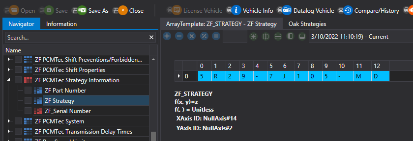
No Luck, still the same. I have flashed in my OEM TCM File (albeit the serial number could not be loaded and pcmtec merged me a new file). The TCM in the new gearbox was 5R29-7J105-LD. The original TCM 5R29-7J105-MD has now bee loaded. Instrument Cluster is not displaying shifter position on reds. When Engine ON and Running blinking "P" HADCHN4 TCM_serial_merged_from_6FPAAAJGSW7K64313.tec Ive move the linkage position at the lever to no avail. Posting my tune file in full to see if anyone has any ideas?
-
Hi Roland. Strategy number remain unchanged. I hesitated loading my original tcm coded "md" ( last two digits) into the working gearbox currently sitting with "LD". My pcm and tcm were originally Desired tranmssion calibration =2 For MD. You also have this in your pcmtec database. I will load my oem tcm file into the tcm and advise.
-
Thank you. I will read the current tcm (newly installed LD) and store it aside. I will then flash my original tcm (MD) into it. I will let you know the outcome.
-
The dash is flashing p,r,n,d,1,2,3,4,5 when in any of the gears. I am NOT in limp mode. The gearbox is changing gears ok, up and down. In performance mode perfect. Only the dash is flashing the gear selected. Dtc is throwing up B2681 (ic) PRNDL sender failure. Car wont start in R and D so it knows the lever and gearbox is in good position. Now whats led to this a new gearbox with valve body. BF2 to BF2. The tcm ive put in 2 months newer than the original strategy 5r29-7j105-LD. The new tcm is 5r29-7j105-MD. I have mateched the numbers in AUF1692 and ZF03987. As mentioned. Car runs, like there is no problem at all. But can seem to stop the dash flashing. Normally on reds, i should see which gear i am in, but cant see it, only when the car is running, very strange. Any ideas?
-
ETC Throttle Angle vs g/s conversion to cm2
Milanski replied to Milanski's topic in Engine Tuning (AUS)
Update to the above, I have installed the twin throttle data for the GT500 and works great! very smooth. Idling at smooth 600rpm and excellent response. -
cool... many thanks. Will now work on high slope and try to find breakpoint
-
Dolan, Engaging 4th gear uses the E-Drum - its calle the dredded e-drum for a reason. For the oil to pressurise the e-drum it passes through the centre of the pump stator. There are teflon seals that keep the oil pressurising the E-Drum. On the other side there is a bush that stops the oil passing. So you rely on seal ring and a bush to maintain good pressure on the e-drum. Most people keep increasing the pressures in the tune to compensate, but alas its a bandaid if the bush is worn or seal rings are not working properly. Then you have clutch wear to deal with. Then there is the valve body itsekf and internal accumulators. I replace all bushes, install new accumulators and vac check the valve body. Use Penrite LV or Lifeguard - ive had good success with either. change the LV regularly. Hope this helps?
-
Hi there, quick update and now I am stuck. I have spent weeks getting the ID1050x data dialed in and I think I have made some good progress. Ex-tuners data simply was wrong and InjectorDynamics data doesnt work either, couldnt even get the engine to crank and start properly with ID Data. I am able to idle at 3 to 4 % STFT and less than 1% LTFT. On light cruise the LTFT seem to be less than 2%. STFT move +/-5% (some cases as high as 10% after decel). On zero foot pedal and coasting I have LTFT at 0.9 or -10% @ 1500RPM for example. Should I just leave it or continue to make changes. Further background information, heavily modified intake, twin turbo 5.4 set up with custom plenum, stock 260 whilst building my engine, some scavenging around the v-bands. I want to get the ID data correct before putting in the new 1000HP engine. For now im thinking of using the VE corrections around 1500rpm / 0-20% load to "work around" the -10%LTFT. Or should I just leave it! Is there anything more I can do to the injector offsets and low slope to fix this, as it seems like im going in circles moving the offsets and slopes. Is there something else to look at? - not sure what accelerator pump is... or hack the speed density tables. I am operating in the smallest range of Injectors capability and understand this area to be hard to dial in, (about 1.4ms PW). I wasting my time? Should I just call it a day? The data below has minimum 100 cell count and tried to keep it in the low slope. Cruise Data: Off throttle data, the flat line is showing OL - Accel/Decl TQ Req. Lean which is net on the list to sort out.


-
ETC Throttle Angle vs g/s conversion to cm2
Milanski replied to Milanski's topic in Engine Tuning (AUS)
Thanks. Tunnel vision, after hours of tuning. You are correct its a multiplier of 7.56 on the x axis. Many thanks. Will confirm the results of the gt500 twin throttle body goes after the tune up. My tune is working with the fg 315 maps for now. Keen to see the difference. -
ETC Throttle Angle vs g/s conversion to cm2
Milanski replied to Milanski's topic in Engine Tuning (AUS)
Reading the table in hptuners does somethiing to the x axis to show it in cm2. In pcmtec its shown in g/s . But i may have to smash them in using hptuners and rwad them back in pcmtec to see the transformation of x axis. Id rather not be using hptuners though, 2 credits... and i am too dumb to dumb to work out how they see it in cm2 and pcmtec see it as g/s... same table. -
ETC Throttle Angle vs g/s conversion to cm2
Milanski replied to Milanski's topic in Engine Tuning (AUS)
Hi puffwagon. I havent changed anything. My pcmtec table shows a different axis label system to hptuners. I uploaded the hptuners file as its not licensed to look at the table for predicted angle vs cm2 vs map. Nothing has been changed. The view in hptuners and pcmtec is different. -
I have GT500 Throttle body from a tune file that has the auF0082 row column labels in "effective area cm2". PCMTEC displays this is as g/s. How it converted from cm2 to g/s? vs the quivalent of the above? Wanting the following data to trial. Disclaimer, not a user of "hptuners", i always use PCMTEC and need to convert the top row to g/s from the HP Tuners file.


-
My battery offset at 13.5V (deadtime) is 0.00118s. low slope is 0.0032lb/s Mim pulse width is 0.3ms Logging is see my InjPW is around 0.5ms on decel. On idle im at 0.9ms. Is the PW value that is being dataligged excluding the deadtime? As time = slope/fuelmas + offset i would expect to be seing p.w. at least 1.18ms.
-
update to my previous post - I have now zeroed out the emmissions table - presto the borderline knock table is in use 100% of the time. Thank you for comments Puffwagon and Roland. BTW how reliable are knock sensors for street tuning - off the dyno tuning. Every now and then a couple of my points pick up -0.3knock retard which I will fix up in the tables if they truely are "knock".
-
trying to get borderline knock to be used at all times, however, there are instances at low load 0.2 to 0.3 where the calc is resorting to MBT tables. An example at 1240rpm, load 0.33, lamda 1.1, iat 37deg. auF16630MBT=27.5, auF16593 BLK = 24.5. This part is good. my MBT table is 3deg higher than borderline. auf2433 - Coolant temp adjustment is zeroed out. The final spark advance is 23deg. For the life of me cant see how this is possible with the above maths: Final Spark = Math.Min(auF16593 + auF0218 + auF0223 * auF0222 + auF0220 * auF0221, auF16630-auF2433). auF0218 = spark lambda = zeroed out auF0222 = ECT running at 90deg = wont be used: auF0220 = IAT running at 37deg = probably around 1 or 2 according to table, this coupled with AUF221 which is 0.1 makes IAT correct if any at all. MBT and BLK tables for reference Could this table: be used somehow in the final spark calc? 5 degree retard is almost the number, but that would be 22.5, whilst y final is 23. Something is pulling 4.5deg and i can find it. in the meantime I will zero this out, to see effect on next run.


-
My WB AFR are sitting about 50mm before the cats. As a test I moved bank 1 (drivers side) upstream to the location of the Ford Narrowband. On bank 2 the O2 sensor remains 50mm before the Cats. Interesting observation --> Bank 1 now read 14.8 or there abouts and bank 2 reads 15.8. Its as if though the Cats are having some sort of effect in that area. It could also mean I have minor leaks on the 2 v-bands between the narrowband and wideband. I have also made a rookie mistake with the turbo set up, i should have welded the O2 bung position on the header before the turbo to take the narrowband. I'm looking at the amount of sources of air ingress between the header collector and narrowband and there are 4 V-Bands... Next engine swap will have the O2 fitted at the headers. As for the injector calibrations, I set the MAP slopes to stock. Set up the fuel tables at 0.9lambda. Adjusted the offset and low slope and honed it in so that under idle I had 13.3AFR (0.9xLambda) and under handbrake+ foot to the brake up to 1500 i had 13.4AFR. (I dont really want to risk going through the garage walls!). I think should be a good starting point. Injector pulsewidth was showing 0.8ms at 1500, only 0.3ms from idle. I am not sure if I am logging the true pulse width, seems very short. Many Thanks
-
Box will take 1000hp no problem. Thankfully rear tyres have little traction for now keeping the diff alive. What input is the flex fuel input, is it the rear o2 sensor input 0-1V? The quick6 has a shift in progress output that is pulled to 0v(ground) during a shift. Ive got an arduino set up to do the tiptronic function between the gear selector (oem ford shifter) and the quick6, therefore i can extend this to be anything i need back to the pcm. Just need to know where to wire it to please. Many thanks.


