

Roland@pcmtec
-
Posts
2,338 -
Joined
-
Last visited
-
Days Won
468
Content Type
Profiles
Forums
Events
Everything posted by Roland@pcmtec
-
Someone PMd a question which I'm posting the reply to here as it gives a good example.

-
Good questions. Most of the parameters can be ignored. I will write up which ones you need to tweak and some more detail behind how the system works. The different terms refer to different parts of the fuel strategy so it is definitely confusing.
-
Up to you. At lower than 100 f coolant temp do you want full spark retard to occur?
-
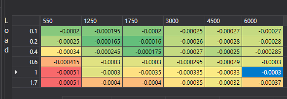
From the factory the Ford Falcon utilises a fairly aggressive throttle cut traction control. This is great for when your grandparents are driving in the rain with standard power. With 300rwkw+ this becomes quite useless and most people turn it off as it allows lots of wheel spin, then kicks in shutting the throttle completely which doesn't make for a predictable or fast car. What is not commonly known is the standard traction control system isn't just a throttle cut, it uses enleanment (or enrichment if you modify it), spark retard and throttle cut. For a performance application we can set up the standard system to simply utilise an aggressive spark retard only. This is very fast acting meaning traction loss is caught quickly, and with the throttle remaining 100% open, you do not lose boost. When coupled with boost by gear and flatshifting, this can mean putting 400rwkw to the ground with street tyres and 100% throttle is possible. It is an absolute must for a fast car. To enable an aggressive spark retard only style traction control system, we will use a lot of the tables discussed in the launch control thread which can be found here. https://forum.pcmtec.com/index.php?/topic/104-howto-bf-manual-launch-control-flat-shifting-and-torque-requesters explained/ There are two guides here, a detail one which describes what each table does and why you modify it. At the end of the thread there is a monkey procedure if you just want to get it happening asap. First we must disable the throttle cut on traction control. We do this by modifying auF0265 and setting "traction control" to 2000. This means the PCM cannot request less than 2000 ft*lb of torque during a traction control event. Eg it is disabled. Secondly we completely disable the ETC cut on traction control by setting the RPM enable setpoint ( auF0264 ) to 10,000 rpm. Technically either of these two settings would do, but to make it clear we disable both. auF0410 ETC Traction Control - Set this to disabled. On FGs there is another function auF11982 "Min torque ratio that can be achieve via spark retard to prevent backfires". Set all the torque ratios above 100°F to 0. Otherwise spark retard will be clipped at 0.3 or higher. Next there are two options, run enleanment during spark retard, or run commanded lambda. From the factory the vehicle will command 1.05 lambda. If you wish you can change this to cause an enrichment instead (safer) by setting auF1479 to something very rich like 0.5 This will mean the vehicle runs 0.5 lambda during a traction control event further reducing power. Or we can disable enleanment/enrichment during traction control entirely by modifying auF0261 and changing the traction control row to 0. This means enleanment/enrichment cannot be used during traction control. In this scenario the vehicle will run the commanded lambda instead. Finally we set the minimum requested torque ratio for spark control auF0262. This controls how aggressive the spark retard will be. Setting it to 0 means the PCM can request 0 ft*lb of torque during a traction control event. This means the PCM will use the maximum spark retard possible which will most likely hit the factory spark minimum clip of -15 degrees. Setting it this low can be too aggressive , personally in a manual vehicle I found a setting of 0.25 to be perfect as it let the vehicle maintain a very small amount of wheel spin. Next we can modify the spark retard transfer function auF2233 (BF only). By setting the very minimum settings to -70 degrees, this means the PCM will very quickly hit the minimum clip. This will affect how fast the PCM reacts to the traction control event, think of it like adjusting the proportional gain. NOTE this table is used for ALL torque based spark retard requestors. If you have an automatic vehicle and you set anything above 0.5 (the default minimum torque ratio during a gearshift) to a lower number you would also affect the minimum spark commanded during a gear shift, this could make your shifts laggy and may be completely unnecessary, for this reason it is only recommended to adjust the 0 and 0.25 cells. Finally auF16586 "Spark Min Clip" can be adjusted below the factory setting of -15 degrees. Note that going as low as -25 will induce backfires and high EGTs, only do this if you are sure your vehicle can handle the high exhaust temperatures. Sitting at -25 degrees timing for an extended period of time can burn valves very quickly and also destroy catalytic converters. Monkey guide: Set auF0265 traction control row to 2000 Set auF0264 traction control row to 10000 Set auF1479 to 0.8 lambda (for safety) Set auF0262 traction control row to 0 to 0.25 depending on how aggressive you want it. 0 is more aggressive. Set auF11982 (FG Only) to 0 for all temperatures above 100°F FG UPDATE The FG uses a much more complicated 3D model instead of auF2233. In the FG the spark delta commanded is calculated using the following equation which is derived from what I imagine is an auto generated mathematical model: Torque_ratio_commanded = 0.8 (eg we are asking for a 20% reduction in torque via spark retard) K = auF1256(rpm,load) K = -0.00032 (4500 rpm and 1.7 load in HAER1UB) Torque_ratio_commanded = 0.8; Spark_Delta = -Math.Sqrt(-(4 * K * (1 - Torque_ratio_commanded))) / (2 * K); Spark_Delta = 25 degrees Knowing this you can see that if you want more torque reduction, you need to reduce K Eg a value of K = - 0.00016 would result in 35 degrees of spark retard. A value of K = -0.00064 = 17 degrees of spark retard. So if we wanted to achieve the same outcome in an FG we would multiply the spark retard table on full load by say -0.5 Here is the original auF1256 table in an FG Here is the new table with approximately 25% more spark retard (will request approximately -35 degrees of spark retard instead of -25 degrees)


-
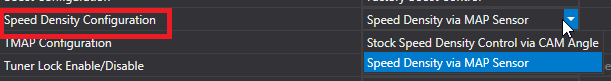
You've just signed yourself up for a fun process! Firstly your injectors must be dialed in perfectly BEFORE installing the camshafts. Eg 1-2% trims. If you haven't you will have a chicken and egg problem. You either need stock injectors and camshafts, or dialed in injectors and camshafts, otherwise you will not be able to tune the vehicle. If your injectors are not dialed in, the easiest way to tune the camshafts will be to put stock injectors back, once you are happy then install the injectors again. There is no way around this, as there is no method to determine if your speed density is incorrect, or your injector slopes are incorrect. Next step, make sure all your speed density settings are standard. Process if you are retaining VCT: I recommend you make sure your camshafts are ground with zero overlap, or you install an offset pin to get 0 overlap. Overlap should only occur when commanded, it shouldn't be present at all times. This is how the factory PCM works and is tuned. If you install camshafts with overlap (almost everyone does) you are going to have a fun job trying to fudge all the speed density maps to make it work. As a result most people end up with a terrible result and stop driving their cars as they become a pig going rich/lean, bad brakes due to low vacuum and stalling all the time. First, do a dyno run and check lambda across the rev range vs your commanded lambda so you have a baseline. Also log both cam angles and camshaft error. If you see large error (eg camshaft gets stuck at 50 degrees) then your VCT cannot control the camshaft and has failed. This is very common with camshafts with high ramp rates and heavier valve springs. If this happens your camshaft will be stuck in a huge overlap position. This results in most of the aircharge going out the exhaust and the car being hard to start. Now something to be aware of, with large amounts of overlap you will have a large amount of air and fuel going straight out the exhaust. This results in your wideband reading a false lean condition (as it measures oxygen, not fuel). So you will have your wideband saying your vehicle is lean and at the same time fuel spitting out the exhaust. If your VCT gear has failed you have two options. Speak to one of the workshops who sells modified VCT gears that won't fail in this manner (Joe at hoontune makes some). Or you can lock your camshafts in place and remove the VCT gears. This is not recommended as your power and fuel economy will suffer, however it is the easiest method to tune. Now assuming your VCT has not failed and is still functional you would move on to the speed density tuning guide and follow the steps found there: If you have installed the camshafts with zero overlap you will find you don't need as drastic changes above and can start commanding more overlap across the rev range and noting power. If you increase the overlap you will need to follow PART4 of the speed density guide linked above. Remember that at large overlap positions you will be getting a false lean condition, so you need to use some educated guesses here. Here is one of the overlap modifiers you can modify. Process if you have locked the VCT Gears If you have locked the VCT gears you can simply use our custom operating system and enable speed density vs map pressure via the guide below: This allows you to do typical VE style tuning where you simply fudge the values at different map pressures to get the result you desire. This is much easier to tune, however you will lose fuel economy and power due to the lack of VCT. As you can see this is not a trivial process. It is recommended that if you are a workshop that you pick 1 camshaft, spend the 2 weeks tuning it perfectly, then only sell that camshaft in the future and use the base speed density tune you have created. If you have random camshafts turning up every week you simply do not have the time to tune it correctly for the money they are paying. Most tuners report it takes well over a week to properly tune the speed density (if you retain VCT) for a specific camshaft. Ford spends half a year with 3 OEM calibrators and a dyno cell to create the stock tunes. Trying to replicate this in a backyard to the same level of quality is simple not possible so you will always end up with some compromises here. edit: This is relevant as well if you are a customer looking at having this done, it might help set your expectations.


-
Work your way towards the stock mbt table in small increments with knock control turned off and knock ears on. Make sure you aren't getting into the iat and coolant modifier regions as that will start pulling timing. Once you are happy heatsoak the car on a hot day and ensure no knock. Then turn knock control back on. Depending on how noisy your motor is you may get phantom knock and need to desensitise the system.
-

HOWTO: Engine Protection Settings
Roland@pcmtec replied to Roland@pcmtec's topic in Falcon HOWTO Guides
A lot of people disable them entirely, I recommend just extending the window so it doesn't occur during normal conditions. As if you get collapsed muffler, melted vac line on the wastegate actuator or coolant leak you definitely want the FMEM action kicking in. Personally I would lower the engine shutdown setting for oil over temp as well. Torque limiting should occur at 130 °C however if you have disabled the ETC clip settings (some people do this without realising) the torque reduction may not actually do anything until it reaches 200 °C Apparently modern synthetic oils still provide lubrication above 200 °C however I would bet other components start to fail before then. You would only see these kind of temps with a pump failure or doing a sustained burnout but it could definitely happen. -
HOWTO: Engine Protection Settings
Roland@pcmtec replied to Roland@pcmtec's topic in Falcon HOWTO Guides
Yes. The CHT is carry over from when the logic used to refer to cylinder head temperature. Some vehicles inferred CHT from oil temp however in the Falcons it means engine oil temperature auF1594 is also oil temp and limits throttle to limit RPM however it needs to be enabled first. To enable auF1594 the oil temperature must be > than the value found in auF0277 which is 275F by default. -
From the factory the Ford Falcon comes with a huge number of FMEM (Failure Mode Engine Management) modes. These are designed to protect the engine from failure when running in severe conditions or under a sensor failure. Some of the different protection modes from the factory are as follows: Boost restricted to spring pressure on intake temperature over temp. Boost restricted to spring pressure on overboost detection. Engine timing reduced on knock detection Engine timing reduced on high intake temperature Engine timing reduced on high engine coolant temperature Fuel enrichment on catalytic converter over temperature Fuel enrichment on exhaust over temperature Fuel enrichment on turbo over temperature VCT disabled on low or high oil temperature. A/C compressor shutdown on high engine coolant temperature Partial injector shut off on extreme coolant or oil over temperature Throttle/torque reduction on wastegate failure (overboost) Throttle/torque reduction extreme coolant or oil over temperature Boost restriction on extreme coolant or oil over temperature Complete engine shutdown on extreme oil over temperature MIL lamp indicator on any of the above failure modes. The following tables (not all) are related to the above failure mode protection settings. auF16463 (wastegate open loop FG) sets the duty cycle to 0.2 on over temp. auF0303 and auF0302 (FG) are the enable/disable setpoints for fuel enrichment to protect a turbocharger. auF16615 control the fuel enrichment for exhaust over temp. auF0196 will enable catalytic converter temperature protection auF0197 is the setpoint upon which to enable fuel enrichment to protect a catalytic converter Knock retard is controlled by various settings under "Knock Sensor" in the navigator. auF0278 / auF0277 CHT (cylinder head) Overtemp refers to the oil over temperature protection enable setpoint. auF1870 is the critical coolant temperature upon which the engine will be shutdown If you don't wish to shut the engine down but instead make it run on half the cylinders you can set auF1613 to a number less than 6 For more information about the CHT shutdown settings see this post here:


-
ZF Swap with different TCM/Megatronics
Roland@pcmtec replied to Turboidiot's topic in Transmission Tuning (AUS)
That is what most built boxes are, upgraded lockup plate and more clutch packs. It isn't as simple as just putting more plates in though as the piston lengths are different (as they run less plates from factory) etc. There are also other changes made eg input shaft etc. -
The sensor is the same however they all have variable resistance. If you were using a wideband controller that has open air calibration that is fine as it will learn the resistance during calibration. Afaik The aem is self calibrating which means if the resistance is different to what it expects it will read wrong. I assume they would be ensuring all the sensors are the same resistance by installing an offset resistor in the loom. Knowing that it means if you don't buy from them it may not read accurately. This is just my assumption though, it may not be accurate what I've said.
-
ZF Swap with different TCM/Megatronics
Roland@pcmtec replied to Turboidiot's topic in Transmission Tuning (AUS)
Just confirmed from a builder that the torque converter is physically smaller (less oil volume) and has a smaller lockup plate. This means it oveheats quicker and the lockup will break under heavy torque. The box itself just has less clutch packs everywhere. The builder said they put a turbo converter in one and it lasted about a year with 350rwkw before it let go. -
It would drive terribly if you disabled it on a box that had learnt the clutch wear.,
-
It seems to be there for me. Did you get an error when it failed? Can you try again?

-
If you have a freshly rebuilt box with extra clutch packs you will find that the car bangs into gears and is generally horrible to drive. This is as the adaptive learning has to unlearn the clutch wear. It takes approximately ~1500km of light cruising to achieve this. We believe the learning algorithm learns forward (eg learns worn clutches) much faster than it learns in reverse, this is as logically a clutch can't become "unworn" so the algorithm probably was not programmed with this in mind. To disable the long term learning algorithm set ZF03182 to 0 To reset the long term learning set this to 0, start the car and put it in gear. Turn the vehicle off then set the variable back to 1. It is reported that it takes less than 100km for the vehicle to learn the clutch wear on a standard box with 150,000kms if this is done. We have another workshop trialling this out on some new boxes shortly to give us some more feedback on how accurate the learning period is and how well this works on a high hp (800hp) build with lots of extra clutch packs. Update: This is not 100% confirmed as working on modified boxes. We have had a report that it does indeed work on a standard box however. Most likely this is as there is only a certain range it can learn as one workshop trialled this on a heavily modified box and found they still had to pull a lot of pressure out of the tune for it to stop banging into gears.
-
ZF Swap with different TCM/Megatronics
Roland@pcmtec replied to Turboidiot's topic in Transmission Tuning (AUS)
It will probably fit up and go in, but the calibration will be different and you'll possible destroy it quite quickly with the extra torque. I have heard of people doing it in sedans, no idea how long it will last or how successful they were though. -
Try these calibrations. They have "GTF" in the notes field, no guarantees they are though. The Ute/Sedan identifier may be incorrect as well but you can probably verify that by looking at the diff/gear ratios and comparing it to what they were released with. HAFH4CD 2012 Manual 5.0 Ute (?) HAFH4ED 2012 auto 5.0 Ute (?) HAFJ1K2 Unknown Sedan HAFJ2Y2 2014 Manual 5.0 Sedan
-
Open vs closed loop boost control
Roland@pcmtec replied to richardpalinkas's topic in Engine Tuning (AUS)
Running closed loop is much more time consuming to tune, as if you don't make the desires boost table match exactly what the open loop duty cycle table shows on the dyno you will end up with a horrible oscillating boost curve when you turn closed loop back on. For this reason most tuners just tune the car in open loop. If you want full closed loop boost control at 20psi the method is as follows. Tune the car in open loop and log the boost against rpm and temp. Set your desired boost table to match what is logged at that temperature and guestimate the other temperatures. Ultimately you want to do a dyno run for all conditions but this isn't possible without a temperature controlled dyno cell. Now reenable closed loop. If you have changed the turbo wastegate actuator or turbo you may need to fine tune the PID gains. This requires knowledge of tuning control systems. There are some good guides online. Even Wikipedia is quite good. Simple guide is if you are getting oscillation (and your desired matches what you see in open loop) decrease the proportional gain and also decrease integral. If you see that the boost never reaches target (undershot) increase the integral gain. The benefit of closed loop is you will get the same boost pressure on 5c and 40c weather. Same with low and high gears. Without it you will see less boost in the lower gears and if you hold it at peak torque in a tall gear you may overboost. This is especially true with the stock gt3582 turbo and actuator which is almost uncontrollable at peak torque and >18 psi. -
Great! Which strategy did you end up finding was the gt?
-
It is only in workshop but I thought you had workshop?
-
There are about 900 strategies between 2002 and 2017 so chances are it isn't. The workshop version of the software has a full calibration list which you can compare certain things between however without the original catch code you will still be making an educated guess. We have listed several of the more common strategies in another thread if you want to compare against them.
-
How do you know HAFFBE2 is the 335? Can you show us the two spark maps from the compare? What is different?
-
I have no idea. This is all second hand information, I've never done it myself.
-
ZF Swap with different TCM/Megatronics
Roland@pcmtec replied to Turboidiot's topic in Transmission Tuning (AUS)
Not a trivial process. There are many different combinations. We couldn't tell you what to do. Also afaik the turbo and na zf are not the same mechanically, I believe the torque converter is different and they have less clutch packs. -
Just found this out via another customer today. If you use the F6 file in a non F6 vehicle you will get a permanent low oil pressure lamp, this is as the loom is inverted in the F6, I believe this is something to do with the factory oil pressure guage that they run. To fix this fault you need to invert auF12646 and set it to 1. If it is set to 0 it will expect the wiring from an F6 to be present.


