

Roland@pcmtec
-
Posts
2,384 -
Joined
-
Last visited
-
Days Won
483
Content Type
Profiles
Forums
Events
Everything posted by Roland@pcmtec
-
Can you give step by step instructions of what you did?
-
 Yes it could.
 -
You can already do anti lag easily. There is a neutral deacceleration timing map (set this to 0 degrees). Disable DFCO, set large cam overlap at high revs and low load, then make 0% throttle 0.5 lambda at high revs. Instant muffler destroying fun. Even with two mufflers it is deafening.
-
We can only repurpose existing sensors. Using the second O2 sensor for flex is a no brainier as most people remove it with their exhaust systems, it also is near the fuel tank and has ground and power. I haven't looked at the electrical drawings recently but if you can think of any other sensors that could be repurpose I'm all ears. Not many people would be keen on using the Ac sensor so it has to be something the majority of people wouldn't miss.
-
You need to use the checkboxes now. You can either click them on the left hand side or use the normal ctrl + click and press space to select them all at once
-
Just double click on the table. I will have a look at the button for you.
-
Initially we are developing the Flex Fuel OS for BF/FG Mk1, FG Mk2 as they all have the second O2 sensor. BA will have to use the power steering pressure sensor or something similar. The second O2 sensor will be connected to an ethanol sensor + controller that outputs 0-5V. Here is the preliminary flex fuel tables we have added. It will then interpolate between the standard 98 tables and the E85/flex fuel table using this lookup: Eg if the flex fuel sensor outputs 2 volts your Fuel base would be: fuel_base = fuel_base_98 * 0.6 + fuel_base_e85 * 0.4 Eg it would use 60% of the standard table and 40% of the alcohol table. If you want a non linear relationship, eg you want to run more timing/boost at full e85 you can do this. Darryl is testing the logic out today on his vehicle and we should hopefully have something for our beta tester workshops in the coming weeks. Another great use of this system is you could use it for dual maps and variable boost. Eg you make all the tables identical except boost you could hook up a potentiometer dial to the input and have variable boost. Or you could simply have a digital switch and switch specific maps to allow for water/meth injection etc.


-
If you tune a lot of cars they are a necessity. You can thank IMS for constantly pushing us to get some of these features out sooner. Eg if you have a value file for most common injectors, open/loop closed loop setup. Boost maps for various turbos and wastegate actuator combos you can build a full tune up in 10 minutes at home before the vehicle even drives in, then all you have to do is trim it up on the dyno. Doing everything from scratch each time is a very time consuming way to tune a car. It is great when you guys ask questions, it helps us fix problems and make the software easier to use.
-
HOWTO: Ghost Cam and VCT simplification
Roland@pcmtec replied to Roland@pcmtec's topic in Falcon HOWTO Guides
Yes if you do this your trims will max out at idle. Fixing the various sd maps will be required as suggested above. -
HOWTO: Ghost Cam and VCT simplification
Roland@pcmtec replied to Roland@pcmtec's topic in Falcon HOWTO Guides
Depends how much overlap you command and how much idling you do. Just tweak it until it drives how you want. Take your laptop with you, you can always adjust it. -
I already have 100 items on my list, don't need anymore at this stage haha. Will you need to do the rest of them now. Are you using 0.71? It should set them all to 6 decimals by default
-
Another way is try double left clicking on the column divider. You have to click on the divider itself.
-
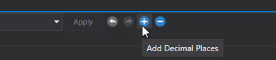
The number is fine. Just drag the header so you can see the whole number, if you can't drag the header then press the + button 5 or 6 times so you get max decimal places, then restart the program and it will auto expand the column for you Once you do that it will look like this To convert from lbm/s to lb/hr you just multiple it by 3600 so 0.031 lbm/s is 111.6 lb/hr Your number will be something like 0.026, 0.03 is rounded up, you need 5 decimal places and you need to drag the header so you can see the entire number. If you leave the defaults in 0.71 and don't change anything it will look like my screenshot.

-
Just drag the column header and make it wider so you can see the whole number. Otherwise if you leave it on the default values of 6 decimal places then restart the program it will auto expand everything anyway.
-
Just expand the column by dragging the header or double clicking on it.

-
Can you show a screenshot? Try expanding the top column in case you just can't see all the digits.
-
+/- doesn't actually change the number, it just changes how many decimal place are displayed. When you click on the number to change it, you always see the full number of decimal places. Units we may add in the future, however it is a huge job to do correctly as some of the units that ford have chosen aren't necessarily correct or sometimes they don't have units at all (when they should) so it is safer to just leave the units exactly as they are in the PCM. lbm/s is pounds per second.
-
HOWTO: Ghost Cam and VCT simplification
Roland@pcmtec replied to Roland@pcmtec's topic in Falcon HOWTO Guides
If you have stock cams providing you don't you don't touch the tables such as "Expected position of cam hardstop" you will be fine. If you change these tables you run the risk of hitting the physical interlocks to stop the cams from causing valve piston interference. If you run aftermarket cams and extend the overlap even further again (no one would do this) via the VCT system there is a possibility of valves making love to the pistons depending on the cam design. The only other risk is fouling your plugs if you leave it idling lumpy for a long time without your air fuel/spark being correct. However that is no different to running actual cams -
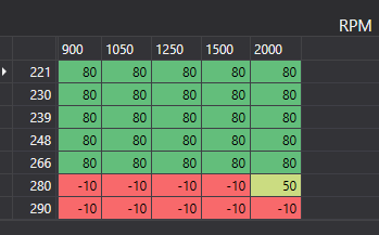
This is a guide to set up a ghost cam on a BF/FG. This involves understanding how the VCT system in the falcon works. NOTE. This is NOT emissions compliant. This cannot be done on a road car, it must be for vehicles that are used on a racetrack or a powercruise event etc. This is the same as using aftermarket cam shafts. The unburnt fuel will not be cleaned up by the catalytic converter and you will be releasing high levels of carbon monoxide (NOx should be quite low as it is running rich, not lean). Do not leave your car idling in a shed with poor ventilation. E85 is much safer than Petrol however it is still not recommended to breath in the gasses. Firstly the VCT works by the PCM calculating an intake camshaft position, it then adds the calculated overlap angle to this position to calculate the position of the exhaust cam. Eg: VCT_Intake_Cam = Calculated Intake position VCT_Exhaust_Cam = VCT_Intake_Cam + Overlap_Angle. Finally to confuse things the PCM then adds/subtracts from the intake and exhaust cam based on boost error. Note this in only in the FGs. This will not affect idle however it will affect your vehicles performance depending on how you have set up the boost control. To achieve a ghost cam we need to understand how the overlap angle is calculated. There are 3 modes of VCT operation cam source == 4 is Idle mode cam source == 99 is VCT Fault/Not Installed mode Cam source == 3 is power/full throttle mode cam source == 2 is part throttle mode. Now in idle mode the camshaft overlap is capped by the same table that determines the intake camshaft position, so you cannot achieve any overlap, the best you can do is set both the intake and exhaust camshaft to 50 degrees which will give you some lump. An easy solution to this problem is to force the PCM into cam source == 3 at all times. This means the main VCT tables are used at all times making tuning the vehicle much easier. To force the camshaft to use the main maps at all times simply set these scalars out of range to -1000 rpm. auF1079 (VCT Closed throttle disable RPM) set to -1000 auF1035 VCT Closed throttle enable RPM) set to -1000 Now to get a ghost cam the following tables need to be modified auF0115 (BF/FG) Maximum allowed overlap angle based on RPM and Oil Temp. Set the lower half of this table to 80 degrees Now we can change the commanded overlap at idle via auF16492 (BF) auF0116 (FG) Here you can see I have commanded 35 degrees of overlap at a TPS reading of 5, this means as soon as you touch the throttle the cam timing goes back to stock making car parks and low load no problem. You also need to modify auF16503 (BF) auF0097 (FG) to have similar timing values in the low load/low tps cells. In this example I set 600 rpm to -30 deg to stop the vehicle from stalling, this will also increase the lope when the rpm drops low as the decreased overlap will kick the rpm back up again. I changed auF0494 (BF) auF16487 (FG) (TPS) axis to 5 in the lowest cell, this means you keep the commanded overlap when hot/cold. Finally I suggest increasing your idle rpm to 1000 rpm to avoid stalling. In the FG there is an overlap adder for speed density auF2260. You will need to put smaller values in the 30 and 60 degree overlap cells. This will clean up the idle fuel trims. BEWARE that some FGs command 30+ deg of overlap when coming onto boost, if you modify this table you may be modifying the WOT fueling as well. If you are using a multi-tune another way to clean up the idle AFRs is to simply add the slope of map table to the tune. auF2928 may be a more suitable table to use for the FGs as it also has an RPM component. It is also recommended to disable LTFT when the ghost cam is active by adding this to your ghost cam tune. This will prevent closed loop fueling from maxing out adding fuel (auF0164) Beware that if you command too much overlap you will foul your plugs and the car will misfire until they clean up. 35 degrees is quite a lot and I would only recommend this as gimmick not in a daily driven car. Here is a video of what the above settings will sound like. As you can see low speed reversing etc is not a problem. Edit: This is possible to do on a BA if you use HAAT3VC or possibly HAAT2xx as these are the late model FPV BAs that had independent cam control. Here is a procedure to upgrade a BA to use the F6 operating system Edit 2: You can increase the lope quite dramatically by modifying this table (auF11706). This is the proportional gain of the idle spark feedback algorithm. By increasing it to 5000 it will toggle between min spark (-7) and max spark (MBT ~25 deg) causing even more lope. This table is only available in workshop edition. In the 5.0 Coyote v8s we have found the figures below tend to give quite a good result without even touching the cam timing. There can be a hesitation when transitioning from idle to throttle, so you may need to add timing to the low load main spark map to help the transition. In the 6 cylinders the numbers don't seem to affect drivability much so you can put silly figures like above without issue. If you are using the multi tune to do ghost cam you can add the following table to the ghost cam tune to increase your idle rpm, this means the non ghost cam tunes can retain a completely stock idle rpm. Here is an example of the required tables in a BF to add ghost cam to to tune 4 only if utilising the multi tune functionality. Value files now available for FG and BF


-
Made a thread specifically explaining spark
-
A few people have asked about Spark so here is a brief explanation of how the ford spark is calculated. The parameter IDs are for BF. FG has more adders as well. The final commanded spark is a combination of multiple tables. This is not an exhaustive list however this is the ones you need to look at. Borderline Knock - auF16593 (this is the maximum spark before the engine will knock) MBT Spark - auF16630 (this is the maximum spark before you stop increasing torque) Coolant temp MBT adjustment - auF2433 Spark ECT Correction - auF0222 This retards timing when your coolant temp gets too hot ECT Correction Multiplier - auF0223 This is a multiplier for the above table. This table can add up to 4 degrees of spark at peak load, make sure you are aware of it. Spark IAT Correction - auF0220 This retards timing when your intake air temp gets too hot IAT Correction Multiplier - auF0221 This is a multiplier for the above table. Spark BLK table adder (lambda correction) - auF0218 - This adds or subtracts timing based on the commanded lambda. This one will catch you out, it makes quite large adjustments based on your commanded lambda, a lot of people zero out the positive numbers in this table. Steady state/cruise This is an approximation of the calculation for when driving under normal circumstances without cold start or deacceleration active. It is an esimation, at some stage we want to make a proper write up on this from exactly what is in the assembly code. This is possibly incorrect or has omissions, so please take this into account. If anyone knows more detail than this please post up any corrections. Final Spark = Math.Min(auF16593 + auF0218 + auF0223 * auF0222 + auF0220 * auF0221, auF16630-auF2433) Or Final Spark = Minimum(BLK + lambda correction + IAT Correction + ECT Correction, MBT-MBT adjustment) IDLE Now if you are at idle it uses a PID loop to control spark. Deacceleration If you are deaccelerating (eg closed throttle) it uses auF0228 (Decel Spark Angle) Cold Start If you are on cold start it uses the following: Maximum Cold Start auF0210 Maximum Cold Start Adder auF0212 Maximum Cold Start Adder #2 auF0211 Cold Start Spark = auF0210 + auF0212 + auF0211 Final Cold Start Spark Max = Math.Min(Cold Start Spark, BLK, MBT-MBT Adjustment) (eg whichever is smaller of the 3 numbers) It will then use the idle feedback algorithm to add/subtract spark to obtain a given rpm. Eg if you have a setpoint of 750rpm and your idle is 700 rpm it will add spark, if it is 800 rpm it will subtract spark. The final figure will be clipped at "Final Cold Start Spark Max" which is calculated above. There is also an "anti stall multiplier" which is added in, most of the time this does nothing unless the rpm dips very low. If you want to datalog final cold start spark max, log the following DMR spk_lold_cld Transient conditions This is when changing the rate of acceleration, eg a change in the rate of load (the derivative of load). For example accelerating slowly, then flattening the throttle. Spark Retard for Tip-In auF0233 Tip in detonation control auF1705 Final Spark Transient = Final Spark (from the above calculation) + auF0233 * auF1705 Torque Control There are various times the PCM will command torque reduction which is achieved by ignition retard and in some conditions ETC (throttle feathering/closing). This is under traction control, changing gears in an automatic etc. Spark Retard (torque ratio) auF0263 Going forward we would like to build a spark simulator. Eg you enter in RPM, Load, IAT and ECT with sliders and you can see what the final spark will likely be, for now you would need to fill out these equations in excel by hand. If you do build anything feel free to post it up, it will be very helpful for others. Why borderline and MBT? Regarding the borderline and MBT tables the reasoning is to achieve maximum timing for performance in all possible conditions. If you use an 120 octane race fuel and find the maximum torque an engine can make then log the spark, this will be your MBT (maximum brake torque) table. Then if you use 91 octane fuel (I think the US fuel is different again) and find the maximum spark the engine can take before knocking this is your borderline knock table. Then you vary the lambda and see how much extra timing the borderline table can take and this creates your lambda spark table. Now this may overlap, eg the borderline knock may be higher than maximum torque. Eg you canrun 50 degrees of timing at cruise however the vehicle will stop making more torque after about 40-45 degrees hence there is no point in running any more. The PCM takes the lowest value of these two tables for this reason. The goal of all these tables and adders is so you can run the absolute maximum timing possible at all temperatures and load. Ford have done a great job of achieving this on a stock calibration, eg the car will run on the ragged edge of knock at all times getting maximum performance and maximum fuel economy (within emissions windows) on 91 fuel. If you were to try and achieve this level of tune in the aftermarket world you would need an engine dyno cell, thousands of litres of fuel and the ability to control ECT and IAT. It would take you a long time, I've been told it takes Ford 3 calibrators 25 weeks to calibrate an engine from scratch. The issue with aftermarket tuning is you do not have the resources to hit each load cell at every single IAT and ECT combination to determine maximum torque and maximum timing. So you compromise and tune the vehicle for the worst case, this means in cold weather/transient conditions you are probably running far less timing than you actually could. Setting the upper loads of the MBT and Borderline tables to be the same figures means you are safe in that you can be guaranteed the PCM will not ever run any more timing than this. It also means at low ECT/IAT temps you will be running less timing and hence less power than is possible.
-
Regarding the borderline and MBT tables this is the reasoning: If you use an 120 octane race fuel and find the maximum torque an engine can make then log the spark, this will be your MBT (maximum brake torque) table. Then if you use 91 octane fuel (I think the US fuel is different again) and find the maximum spark the engine can take before knocking this is your borderline knock table. Then you vary the lambda and see how much extra timing the borderline table can take and this creates your lambda spark table. Now this may overlap, eg the borderline knock may be higher than maximum torque. Eg you canrun 50 degrees of timing at cruise however the vehicle will stop making more torque after about 40-45 degrees hence there is no point in running any more. The PCM takes the lowest value of these two tables for this reason. The goal of all these tables and adders is so you can run the absolute maximum timing possible at all temperatures and load. Ford have done a great job of achieving this on a stock calibration, eg the car will run on the ragged edge of knock at all times getting maximum performance and maximum fuel economy (within emissions windows) on 91 fuel. The issue with aftermarket tuning is you do not have the resources to hit each load cell at every single IAT and ECT combination to determine maximum torque and maximum timing. So you compromise and tune the vehicle for the worst case, this means in cold weather/transient conditions you are probably running far less timing than you actually could. Setting the upper loads of the MBT and Borderline tables to be the same figures means you are safe in that you can be guaranteed the PCM will not ever run any more timing than this. It also means at low ECT/IAT temps you will be running less timing and hence less power than is possible.
-
It won't completely disable the torque stuff. Eg traction control will still utilise the throttle to control traction by shutting it under extreme traction loss. I've tested and confirmed that in a manual however I'm pretty sure all the fuel and spark torque stuff is disabled as it makes the traction control quite on/off eg it does nothing or it puts your head through the windshield.
-
Have a read of this thread
-
This is an interesting one. It looks like ford have done something interesting to the ECT spark scaling table in HAEE4, I checked 4 of the stock files and they all are similar to this. At 68c you are 154f which would make it ((200-140) - (154-140)) / (200-140) = 0.76 0.76 * 40 degrees = 30.6 * 0.1 = 3.06 degrees timing So 10 + 3.06 ~= your 13 degrees you are seeing As 13.3 is less than your MBT table (~20 degrees) this all makes sense. This is why some people make their MBT identical to their Borderline table. So it looks like this is your problem. as the MBT table is calibrated at 200F it makes sense that you can run an extra 4 degrees of timing at 140F, the -18 (1.8 degrees) would be for cold start/emissions purposes. Remember that these figures would have been for a stock turbo. So easy solution is simple zero out all positive numbers in the IAT (auF0220) and ECT (auF0222) adder. It looks like you've already done that for IAT.


