

Roland@pcmtec
-
Posts
2,384 -
Joined
-
Last visited
-
Days Won
483
Content Type
Profiles
Forums
Events
Everything posted by Roland@pcmtec
-
PCMTEC Editor Version 0.62 has now been released as of 27/3/18 To download please login then visit https://www.pcmtec.com/downloads This page is only available for customers who have purchased the full version of the software (Enthusiast, Professional and Workshop). The demo has also been updated to version 0.62 which can be downloaded here (you must be registered and logged in) https://www.pcmtec.com/demo 0.62 is an interim release that has the following bug fixes/improvements: Improvements: Compare view now supports fixed decimal places which can be adjusted by pressing the +/- buttons on the screen. If you now select multiple cells, type a number and press enter all the cells will update. Removed the requirement to enter address/name etc from the login page. These are now automatically populated from the server requiring only your username and password. PCMTEC Editor will now work behind a corporate proxy. It does this by pulling the proxy configuration from internet explorer and uses the windows cached credentials to attempt to re-use existing proxy configurations. Bug Fixes: Compare/Change History View columns and commas were broken. This view is now vastly improved display correct spacing making it much easier to use the compare/change history functions. ZF signed bytes were displayed as if they were unsigned (small number of ZF scalars) showing odd values. Further performance improvements to compare view and table view. On first open of the program tec files are now blocked from opening before Globals and Templates have downloaded. This stops the "Licensed .dat file could not be found, we will now attempt to download it" which could occur on a fresh install. When no J2534 cable was plugged in and you were using a high DPI (4K) monitor after pressing "Read Flash" the "Select Device" popup was partially hidden making it appear as if the program had frozen.
-
Yes it appears it is much easier than we originally thought to offer custom axis inputs etc, originally it just seemed like the effort would be too much however that is no longer the case. The hard bit will be getting the UI to dynamically allow a user to change these. Currently we are manually editing the binary. We have come up with a procedure to implement this dynamically in the UI, however it will take some time to implement it. Ultimately if we get this custom OS working as we have planned, you will be able to select any DMR at all as an input to the Axis, this would open up a massive amount of possibilities, effectively making the PCM almost as flexible as an aftermarket one such as a Haltech etc. To answer you question, if you wanted to boost by gear in a BA/BF then yes you would need to use a custom OS. Currently I believe only the Sprint etc have boost by gear which is only compatible with the FG (mk2 I think?) PCMs.
-
You can read the file and save it to disk as as backup however you will not be able to view or edit it until it has been licensed. Once the file has been licensed at least once, it can be sent to anyone else and they can view it and edit (but not flash) it. So to be able to a view someone else's tune someone must have licensed the .tec file at least once previously. This is how our stock database works, we license the files internally then package them all up so they can be viewed and compared. The advantage of this system is you can send your tune to your mate/tuner, they can edit it and send it back to you. Other products don't allow this.
-
I suspect you will reach your goal much quicker with out one. You said you raised the lambda at 0% throttle? You want to lower it, lower numbers are richer. If you set it to something stupid like 0.5 it should do something! Beware of damage to your spark plugs/cat/exhaust system though. Please don't take this as advice though, you could damage something.
-
Do you have a cat?
-
Hi Jason. I've never tuned a 5.0 before, could you explain what you mean by throttle limit? This is something that would be good to get a community response on. If you know anyone else who knows more send them a link, once we get enough info we could compile something.
-

Pro License feature: Return to factory calibration (stock)
Roland@pcmtec replied to molch's topic in PCMTEC Editor Questions
Yes that is the strategy code that you need. However that may not be what the car came out of the factory with if it'd been previously tuned. The catch code inside your door will help us determine what it was at release. Next release depends on the volume of support requests and issues we run into during development. Won't be too long, most likely weeks not months away. -
Pro License feature: Return to factory calibration (stock)
Roland@pcmtec replied to molch's topic in PCMTEC Editor Questions
Providing you know the original strategy or catch code (should be in your driver's door) we can restore the car to stock. This feature will be in the next major release. -
Disabling dfco (eg set the delay time to several minutes), setting deaccel timing to 0 degrees and disabling closed loop O2 sensor at all loads above x rpm will make for some extremely loud cat destroying backfires. If you mess with commanded fuel table to make it richer at no throttle I imagine you could get flames. Beware of damage to your turbo, mufflers and cat though. Wouldn't do this on the street as the backfires will be loud enough to hurt people's ears.
-
Thanks for the support! Right now we are just concentrating on getting our sales to the point where we don't have to do any supplementary work. They are currently trending steadily upwards so it is looking promising. We have had 87 cars tuned with PCMTEC since October. Once we get a steady income we hope to be able to employ others to help take the load off us. Then Darryl and myself can concentrate on just pumping out code all day and move the focus off the day to day activities. We both love programming and really enjoy this work, so far it still feels like a very enjoyable hobby which considering I've been programming for almost 10 years surprises even myself. A lot of people have said it felt like a job to them a long time before that. End goal is to make this software better than the competition in all ways for the Australian market. Initially we would like to polish and perfect a smaller number of vehicles, rather than spread ourselves thin supporting lots of vehicles but not doing it so well. Other vehicles like GM and Subaru have great tuning platforms however it appears many still lack good software so plenty of room for us to innovate.
-
Hi Molch When is the first release scheduled? Only a rough estimate at the moment however middle of the year is what we are estimating. What are the likely supported parameters? Darryl has already done a lot of the mapping for the parameters. We aim to support the X and Y input of every single table and the Z output where possible. So each parameter will be named after the table the value is datalogged from with _X _Y _Z etc. This will remove a lot of the guessing as you know exactly what you are datalogging. Along with the above DMRs we will log all the final values for spark/airmass etc. We will also support all the standard PIDs etc, though these are often not exactly what you expect and lead to confusion when datalogging other products. Personally I don't think the PID logging is very useful compared to DMR logging. Will we be able to log correct airmass? As above. Yes. Will it scan injector pulse widths and will it include deadtime? Yes these sort of must haves we will do our best to include. Basically if the PCM stores them in RAM we will add them into datalogging. Currently we have mapped roughly ~6000 DMRs for HACCK and ~8000 DMRs for HAEDH the PCM. We will also build smaller sets of "useful" parameters, as most of these DMRs are not things you would normally want to log unless trying to diagnose a very specific problem. Any other tricks or tools for general fuel / sd tuning? In the future we want to add "Wizards" and various helpers for these things. Eg a visual graph with the injector deadline, low and high slope that you can drag around to visualize the impact on fueling they will have. Will there be a way to line up afr's from a wideband? We plan to allow datalogging any wideband that supports serial/usb logging providing we can get a loan cable. These logs would then be within the DMR log so no having to line up time stamps and frustrating things like that. This would most likely come in a future release. Ngauge Support There is no technical reason why not. Currently we are speaking to nGuage and are discussing getting access to do this. Due to their business model this would most likely involve a new PCMTEC nGauge and converting your HPTuners gauge, it would not be able to store both formats simultaneously (even though technically it would not be an issue). We aren't huge fans of this concept so the other option we are looking at is building an Android phone app that connects to the OpenPort cable to achieve similar functionality as the nGuage. Lots of commercial opportunities in this space so we welcome any suggestions from others who may be able to assist.
-
We don't have any other DEMO files, you will need the full version to view other tunes. If you compare the xr6 sprint, f6 vs non f6 etc you will get an idea of the timing changes ford makes.
-
They will ping standard with no changes. The knock retard is quite heavy though so you can double the boost, it will knock and then it will pull up to 14 degrees of timing for you automatically. Absolutely wouldn't recommend you tune like this but some people do and the cars will survive for longer than you think. Have a look at some tuned cars. They will run quite low timing at peak torque. So to answer your quest they aren't conservative at all.
-
Note this guide is an approximation and may contain errors. Caution should be used when using the assumptions made here. The parameters listed here are for BA/BF only, FG uses different parameter names. A separate guide for FG will be added later. Boost Control The BA/BF/FG use two main modes for boost control, open loop and closed loop. FG also uses a third addition which is feed forward control based on RPM. Initially they operate in open loop mode. This is similar to an aftermarket controller eg eBoost etc where you set predefined gains and the system does not rely on any feedback. In open loop mode if your wastegate actuator lost preload over time or failed completely your boost levels could vary wildy. In open loop mode the system uses the following wastegate duty cycle auF0307 - The openloop wastegate duty cycle, used to achieve the desired boost in close loop boost control or the actual wastegate period when in open loop boost control. Closed loop. Closed loop is where the PCM measures the boost pressure and constantly adjusts the wastegate gain using a PID controller The PID controller will use the following table as its setpoint to reach the desired boost auF0306 - The desired boost pressure. A PID Controller works in the following method. Every millisecond it executes the following function (approximation) Error = Desired Boost (auF0306) - Actual Boost (from boost sensor) Wastegate Duty = Open Loop value (auF0307) + Error * Proportional Gain (auF0287) + Error * IntegralSum * Integral Gain (auF0286) This means the Wastegate duty will be added or subtracted to based on the error. A larger error will mean a larger adjustment to the wastegate value. auF0287 - PID Turbo Proportional Gain auF0286 - PID Boost Integral Gain auF11628 - Desired Boost Pressure hysterisis term. The PID controller also uses a hysteresis (deadband) value. This means if the actual measured boost is within +- (auF11628) inHg it will not further modify the wastegate value. This means your measured boost may have an error of within +- 1.46 psi under normal circumstances. auF2776 - HYSTERESIS FOR OPEN LOOP WASTEGATE CONTROL If the boost error (desired - actual measured) is less than 0.15 inHg (0.07 psi) the closed loop PID controller will be disabled and only the open loop duty cycle will be used. This means if your open loop duty cycle table is incorrect you may see oscillations in your boost level as the closed loop PID controller is enabled/disabled over and over again. auF0296 - OVERBOOST REQUIRED FOR OPEN LOOP DUTY CYCLE auF1890 -OPEN LOOP DUTY CYCLE FOR OVERBOOST If the measured boost error is greater than auF0296 inHg (-40 by default) the PID controller will be disabled and the wastegate will be set to auF1890 (0 gain by default) auF2577 - UNDERBOOST REQUIRED FOR OPEN LOOP DUTY CYCLE auF1898 -OPEN LOOP DUTY CYCLE FOR ONDERBOOST If the measured boost error is greater than auF2577 inHg (40 by default) the PID controller will be disabled and the wastegate will be set to auF1898 (gain of 1by default) auF2977 - Boost Pressure error deadband to allow feed forward adaptive control (FG MK1 onwards only) auF2646 Turbo feed forward adaptive wastegate position based on current rpm (FG MK1 onwards only) Feed forward control is enabled if the error is within 1.5 inHg (auF2977) and open loop control is active. This is added to the wastegates final position in the PID calculation to attain better control. If the wastegate has been modified in any way this may cause issues with boost control if it is not modified. DTC Error State When the boost error is > auF1098 (typically set to -5inHG) it will trigger an overboost DTC code P1227. This is a DTC code only, this does not actually set the duty cycle to 0. The duty cycle will be set to 0 via auF0296 . It is possible to leave the DTC enabled but leave the action disabled by only setting auF0296 out of range but not setting auF1098 out of range. Tips if your open loop gains are incorrect the PID controller will have a hard time reaching the setpoint. When tuning you should set the PCM to use open loop only by setting all gains to 0. Dyno the vehicle and ensure your measured boost matches your desired boost table as close as possible, only then enable closed loop afterwards. This will result in your actual measured boost matching your desired boost table with far less deviation from desired. If you modify the turbo/wastegate system you may need to modify the PID gains to account for a faster/slower responding wastegate and also to compensate for additional wastegate flow. Operational modes Error between 0 and +-0.15 inHg closed loop will be disabled and the open loop values will be used. Error between +-0.15 and 3 inHg closed loop will remain enabled however the wastegate position will not be adjusted. Essentially the PID will be frozen and hold last value. Error between +-3 and 40inHg closed loop will remain enabled Error +-40inHg Over/Underboost will be activated. Error between 1.5 inHg and 40inHg Feedforward control will be active (FG only) Overboost Some calibrations allow temporary overboost under specific conditions. Explanation will be added later. Boost by gear Boost by gear is available in the XR6 Sprint calibration from the factory. Otherwise using our custom operating system you can enable boost by gear or speed. This requires the workshop edition of the software.


-
Correct the table is TPS vs RPM not Load vs RPM like you would see in non speed density tunes. If your injectors are scaled correctly and the speed density is setup correctly it should be as trivial as setting the AFR you want in that first table and it will hit it regardless of load, eg if you ran 10psi or 20psi at full throttle, you should see the commanded lambda in the TPS table the same as what you measure with your wideband. If you wanted different AFRs at different load points you can fudge it using these tables, this will throw out your commanded lamdba vs actual lambda though which could have side effects in other parts of the tune.

-
We are happy to release the next major beta release of PCMTEC Editor Version 0.50. The following new features have been added: Change History This is a large update. Change history is displayed as a tree with the same layout as the navigator. Each change you make in the program is recorded and saved. Each individual change can be "applied" to revert the change.. Each time you save the program a new "Session" is created and each change is stored in its session. There is also an "All Items" session which shows all change history ever made to the file. Selecting between each "Session" will show changes made in that session only compared to the current state of the tune. TableView Change History Individual tables now also show their change history that is displayed in the same fashion as the "Compare/History" overview. Each change history item can be selected and viewed by clicking on the list entry. You can scroll through them all by using the up and down arrows on the keyboard. Should want to revert to a specific history item simply press "Apply". ScalarView Change History Scalars have the same change history as found on the TableView. You can scroll through the historical values from the history drop down. The historical value is shown under "Historical/CurrentValue". Once again you can revert to the change history value by pressing "Apply". Undo/Redo You can now undo/redo within tables and within scalar lists. To undo simply press Ctrl + Z. To redo press Ctrl + Y. Or you may use the new Undo/Redo buttons located at the top of the table viewer. This will allow you to undo all changes made to this table/scalar. Stock Files This is another major change. We have now added automatic downloading of stock files for vehicles you have licensed. These stock files are stored in my documents with your settings. These files are automatically updated to show new parameters. These updates are performed each time you login. Each of these stock files is now loaded into the change history of your licensed TEC files allowing you to compare all of your files against the stock values. This is done automatically when you open a file. This will show you the stock value "Compare File" vs your current value. From this screen you can return bulk values to stock by selecting "Stock" from the drop down list. Entering "Stock Value" into the search panel, selecting all items (Ctrl+A) then pressing "apply". This will revert all known parameters back to their original values. Care should be taken with this. You can also view the stock value via the TableView and the ScalarView and easily revert one value at a time. Compare You can now load unlimited compare files. Compare files are loaded via pressing "Load Compare File" from the Compare/History popup. You can then select each file from the drop down one by one and compare the changes to your current file. The same drop down is visible on tables and scalars. Recent file history can now be accessed from the File menu. DTC Codes DTC Codes can now be read and reset from the "Vehicle Info" screen. A DTC reset is now performed after a flash read and write to ensure lost comms DTCs are cleared. Log Visibility For those of you with smaller laptop screens the Log can be hidden (until an error occurs) via the View menu. This setting is remembered until you untick it. Minor changes Ability to single click anywhere on the navigator groups to expand them. Eg single clicking on "Scalars" will now auto expand/close the list of "Scalars. When clicking on an invidivual scalar from the navigator it now automatically scrolls the scalar view to show you this scalar. This helps you find the parameter when looking through the large lists of development parameters. Scalar View/Navigator Colour Updates. We now use a traditional pink/red colour to indicate a value is dirty (has changed but has not been saved). Blue to show a selected item and yellow to show search item text. Scalars now have maths available to them! This works in the same way as the TableView maths does. Bug Fixes Entering ".55" into the maths entry will automatically edit and append the text to "0.55". Previously it would convert to "55. Attempting to read a vehicle when not logged in would give an error saying the vehicle was not supported instead of "Must be logged in" when attempting to license the vehicle. Improved consistency of units and use SI where possible (this should be already visible in 0.41) Can now enter spaces into char/string fields. Next Release: The next major release will be to add support for flashing and editing the ZF 6HP 6 speed transmission. We will have a demo file available shortly to allow you to view what parameters will be available.


-
Loki just following up how you went with datalogging and scaling to suit as per the email discussion with Darryl?
-
This is where we can shine, with our Australia first attitude it should help fill this hole over time as this will be our only focus until we are confident is is the best piece of software available to tune the Falcon platform.
-
Mick when you say bricked PCMs do you have any information on which strategies will cause them to brick? If you still have the PCMs I'm curious if we can recover them, this is mainly so we can make a list of transitions and block people from doing it in the editor if it is not reversible.
-
Hi Loki, Afaik these cells are not used at idle, only when transitioning from idle to throttle. Firstly the idle should be stable with the stock settings, if you have to modify them it suggests an issue elsewhere. Places to look at your idle airflow, dashpot, injector scaling, injector offset and even physical idle air control issues. If you find the problem is still there the idle spark is controlled via the following items: auF2429 Idle Spark Proportional term (the P in the PID Controller) auF0215 Spark Idle Minimum (PID controller will clip at this value) auF16507 Spark Max (not just at idle but all the time) auF0015 Adaptive Idle Control range (typically 30rpm) if the rpm error goes outside of this range it will go to the normal open loop spark tables. This may be why you see the spark value flicker at idle if the error becomes too large. auF0020/auF0021 Idle RPM in Gear/Neutral - If you have a mechanical problem meaning the idle is quite a distance from this value you will also have issues. auF1920 Max spark for low load - Afaik this will limit idle spark, personally I've not tested it though. auF0213 - Max spark for idle in gear- I've not tested this either auF0214 - Similar to the above but in neutral If you aren't aware of what a PID controller is, have a read on wiki. It is effectively a mathematical equation that looks at error terms. Eg: Error = Desired Idle Spark - Actual Idle Spark Spark Adjustment = error * P Then there the integral term as well but this is fairly complicated so I won't get into it. Another way to think of a PID controller is imagine you are in the shower. The shower is cold so you turn on the tap (the spark adjustment). Eg 40 - 0 = error. Error * P = adjustment. You turn the tap too much so shower becomes too hot (now a negative error) which means error * P means you will now turn the tap the opposite direction. In this example your brain is the PID controller, the setpoint is the perfect temperature, the actual temperature is the water temp and the controller output is your arm turning the tap. A PID controller constantly makes adjustments based upon error in the same fashion. Closed loop boost control uses the same type of PID controller. Eg it measures boost pressure vs what is in the map and calculates an error term and adjusts the bleed gain based on this error. https://en.wikipedia.org/wiki/PID_controller https://www.csimn.com/CSI_pages/PIDforDummies.html
-
No problem, it is a bit daunting at first but you will see that you can simplify things quite a bit. A lot of people start by zeroing the lambda correction table and setting BLK and MBT to be equal. They also zero the positive numbers in the IAT and ECT tables, this way what you see in BLK is what you get and only once the motor gets hot do the IAT and ECT tables kick in and start pulling timing.
-
Hi Loki the spark algorithms are far more complex than simply Load vs Rpm. The final commanded spark is a combination of multiple tables. This is not an exhaustive list however this is the ones you need to look at. Borderline Knock - auF16593 (this is the maximum spark before the engine will knock) MBT Spark - auF16630 (this is the maximum spark before you stop increasing torque) Coolant temp MBT adjustment - auF2433 Spark ECT Correction - auF0222 This retards timing when your coolant temp gets too hot ECT Correction Multiplier - auF0223 This is a multiplier for the above table. Spark IAT Correction - auF0220 This retards timing when your intake air temp gets too hot IAT Correction Multiplier - auF0221 This is a multiplier for the above table. Spark BLK table adder (lambda correction) - auF0218 - This adds or subtracts timing based on the commanded lambda. This one will catch you out, it makes quite large adjustments based on your commanded lambda, a lot of people zero out the positive numbers in this table. Steady state/cruise This is an approximation of the calculation for when driving under normal circumstances without cold start or deacceleration active. It is an esimation, at some stage we want to make a proper write up on this from exactly what is in the assembly code. This is possibly incorrect or has omissions, so please take this into account. If anyone knows more detail than this please post up any corrections. Final Spark = Math.Min(auF16593, auF16630-auF2433) + auF0218 + auF0223 * auF0222 + auF0220 * auF0221 Or Final Spark = Minimum(BLK, MBT-MBT adjustment) + lambda correction + IAT Correction + ECT Correction. IDLE Now if you are at idle it uses a PID loop to control spark. Deacceleration If you are deaccelerating (eg closed throttle) it uses auF0228 (Decel Spark Angle) Cold Start If you are on cold start it uses the following: Maximum Cold Start auF0210 Maximum Cold Start Adder auF0212 Maximum Cold Start Adder #2 auF0211 Cold Start Spark = auF0210 + auF0212 + auF0211 Final Cold Start Spark = Math.Min(Cold Start Spark, BLK, MBT-MBT Adjustment) (eg whichever is smaller of the 3 numbers) Transient conditions This is when changing the rate of acceleration, eg a change in the rate of load (the derivative of load). For example accelerating slowly, then flattening the throttle. Spark Retard for Tip-In auF0233 Tip in detonation control auF1705 Final Spark Transient = Final Spark (from the above calculation) + auF0233 * auF1705 Torque Control There are various times the PCM will command torque reduction which is achieved by ignition retard and in some conditions ETC (throttle feathering/closing). This is under traction control, changing gears in an automatic etc. Spark Retard (torque ratio) auF0263 Going forward we would like to build a spark simulator. Eg you enter in RPM, Load, IAT and ECT with sliders and you can see what the final spark will likely be, for now you would need to fill out these equations in excel by hand. If you do build anything feel free to post it up, it will be very helpful for others.
-
FYI being able to copy over differences yourself from the Compare viewer is not far off. ZF flashing is likely to be the new year, we can get you an editable (but not flashable) copy of your ZF trans into the editor in the mean time if you are curious what kind of parameters you will be able to view. "The VCM license will only work with the original calibration assuming it is already licensed" Whilst this is true there will be nothing stopping you from flashing the old non boost by gear file back into the car should you wish to use HPTuners again, you just won't be able to edit the Sprint OS with HPTuners unless you license it again.
-
How to copy paste multiple cells?
Roland@pcmtec replied to Roland@pcmtec's topic in PCMTEC Editor Questions
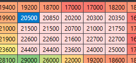
Press and hold the left mouse button to select the cells you want to copy. Or press and hold shift and use the keyboard arrow keys to select multiple cells. Press Ctrl+C to copy to the clipboard OR right click and press copy. To paste select the cell where you want the paste to begin. Eg it will paste from left to right and up to down.

-
How do you copy paste multiple cells at once?


