

Roland@pcmtec
-
Posts
2,338 -
Joined
-
Last visited
-
Days Won
468
Content Type
Profiles
Forums
Events
Everything posted by Roland@pcmtec
-
Have you used a manual strategy? There is a lot of stuff that usually needs changing in the cal, a lot of its in workshop only.
-
V8 5.4 all rows are the same so a bit easier. Don't need to touch slopes for stock injectors
-
Not sure if you can turn off the trimming logic and still have the heater on. I think as soon as it detects a failure it turns it off. I don't see why you couldn't splice the primary narrowband though.
-
It estimates the exhaust/catalytic converter temperature and turns it on at 550°F I believe. It is configurable and uses PWM to control the heater circuit.
-
An idea, put a relay off the narrowband heater circuit, then wire the power through this. The heater is PWMd but the relay should smooth that out and only trigger once its at full power.
-
Some of the big workshops I know change their sensors every fortnight. Its cheap if you are using it daily.
-
They are usually killed by water. If you turn the controller on (the heater circuit inside of it is the issue) when there is still moisture in the exhaust and it hits the tip it will kill it very quickly. The internal heating circuit will get the sensor to about 500c from memory, 500c + water = cracks. The best way to run the wideband is to ensure it is not powered on until the engine is no longer spitting water out the exhaust. Mounting the sensor at 10-2 o clock will assist the moisture avoiding it, but it can still happen. Some controllers have excellent heating circuits with timers etc, you could also log the heater output from the actual PCM itself and use this as a gauge when the PCM turns the narrowband sensor on. Heat will kill them also, but that is more a long term thing.
-
Good info there
-
There are individual knock trims per cylinder and also an average knock adder that you can log. The following two items are what your want to log Individual cylinders SPKAD_IND[0-7] Average total SPKAD_IND_AVG Regarding spark have a read of the link below. Short answer is you can pick either.
-
What @misk said. Some more information here:
-
I can't help you with the data however I can help you make the process a lot easier for yourself. Do you still have the stock injectors? You can pick them up cheap if not. Personally I'd put the stock injectors in and get the speed density mint. Then sort out the injectors after. Also are the camshafts locked? If so and you have the workshop edition we have a traditional VE style speed density patch (Enabled via the Custom OS Wizard) which changes the Y-Axis from Intake cam angle to MAP pressure. Then you can fudge the speed density based on MAP pressure to help account for reversion at the low rpm. This makes the speed density tuning MUCH easier as its like tuning a VE map on a commodore with no VCT.
-
Thanks for the update Tyson, I'm sure it will be useful for people.
-
@Tyson Curious how you went with this? We just had an enquiry about the BTR and I pointed them here for some more information.
-
 How lumpy are the cams? Do you have long term fuel trims still enabled? If so what are your long term fuel trims? You want them under 10% for acceptable low load/idle/cruise driving without stalling or flat spots. This can be very time consuming to achieve with camshafts. If they are lumpy with lots of overlap its best to tune the car in open loop, otherwise the false lean condition (due to the overlap) at idle will cause it to run rich and stall. If you have VCT I'd personally tune out the lumpyness at idle, the VCT is very versatile and you can effectively do a reverse ghost cam. Have a read of this as well which might help set your expectations.
 -
If you have Enthusiast you can upgrade online for the difference in price. There is an upgrade option available.
-
Professional is required.
-
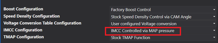
Ever wanted to have nitrous automatically controlled with no external controller? What about staging a 2nd fuel pump? How about water meth? Using the following instructions you can automatically stage nitrous to turn on at a specific rpm/map pressure and only in a specific tune. You can also wire a feedback signal back to the PCM to automatically change the tune to one with different fueling/spark depending on the application. For other applications please read this guide. Eg for water meth you may want to use a low level switch to automatically switch to a tune with more fuel and less spark when the tank runs dry. Step 1. Open the custom operating system wizard and select Multi Tune Next pick "Flex Fuel Sensor" and select "Custom Voltage Input Table" Next step is to add the IMCC enable/disable rpm setpoints to the multi tune. Also add these scalars to tune 2,3,4 on the next page. This will allow you to configure which tunes the nitrous/water meth is switched on. The default is 3800rpm. Finally we need to enable the IMCC output auF1703 by setting it to 1 Nitrous Setup To configure nitrous to turn on in tune 4 and during launch control to assist with spool set the following values. Make sure to set these values for all 10 tunes, both the 98 (nitrous) set and the e85 (no nitrous) one. To confirm the above is working you can datalog the "IMCC" value in the datalogger, a value of 1 means 0v, a value of 0 means 5v is available at pin B03/1106. Note that when the IMCC is referred to being closed the PCM supplies an open circuit, when the IMCC is open it supplies 5v. Now that the IMCC output has been configured to setup the nitrous output we need to setup the no nitrous tune (98) with normal spark values. This can be done by adjusting the "Tune 1 Base Tune for 98" spark map. Next we need to tune the nitrous spark/fuel maps. This can be done by tuning the "Tune 1 Base Tune for E85" spark and fuel maps. First we need to set the stoichmetric ratio correctly. In our case we are using 98 octane fuel so we need to set the entire stoich table toe 14.64, this is as we are repurposing the flex fuel tables to use with nitrous and not alcohol content. Next step is to configure the analog input used for feedback to toggle the nitrous maps on/off. To do this we set the high/low map usage to toggle at 1.1v to 100% of the e85 (nitrous on) tables. Below 1v we get 100% of the 98 (nitrous off) maps. The final step is to wire up the nitrous to the IMCC output and then wire up the feedback to the Rear O2 sensor. The recommended way to do so is to cut the nitrous system when the clutch is let out, and also have a master override switch in the cabin. This means even if you have a nitrous map selected (tune 4) from the steering wheel, you can still disable the nitrous system if needed. Using the schematic below we can see the following parts are needed. Cabin override on/off switch with normally open contacts. Toggle push button switch with normally open contacts to be installed on the clutch bracket. A 5v relay with normally open contacts that is rated to enough current to power the nitrous solenoid. Note. You do not have to wire nitrous enable feedback to the PCM, and can instead assume when the IMCC output is on, nitrous is also on. This means skipping the steps to enable the flex fuel logic and instead modifying the spark/fuel values in tune 4 98 octane directly, and not in the e85 (nitrous on) tune. This is a simpler way to set the system up. If the nitrous is not actually on and tune 4 is selected, then the tune will simply run retarded spark and rich fueling which will not risk the engine so this may be satisfactory. Water Meth: If you are planning to install a water meth system with a low tank level cut out switch follow the instructions above for nitrous and instead use the following schematic which uses a second relay for the low level switch Note: You do not have to wire a water meth low level switch and can instead rely on the fact that water meth drops the charge temperature, knowing this you can datalog the expected temperature drop, if its not within the expected range you can add significant timing retard to the IAT spark adder table auF0220, this will enable the engine to still safely function in the event of a water meth failure. The recommended way however is to use a flow sensor or low level switch. Staged Fuel Pump: The above logic can also be used to trigger a staged fuel pump or any other accessory which requires a window switch.


-
This guide covers how the idle control on the Falcon platform works. Short Answer: This assumes you have under 5% LTFT and have not changed the throttle body. If your trims are > 5% you need to fix your injector scaling, if your throttle body has been changed you need to adjust the throttle tables. If the above items are correct and your idle airflow is still wrong due to large camshafts or a large change in engine VE, then you need to adjust the open loop portion of the idle equation. To do so first ensure you are in closed loop idle mode by datalogging IDLE STATUS MID49718 "Idle Speed Control Mode Flag" and the mode is (1) Rpm Ctrl Mode or (2) Rpm Ctrl Learn Mode -2=Drive Mode -1=Dashpot 0=Dashpot Preposition 1=Rpm Ctrl Mode 2=Rpm Ctrl Learn Mode Next datalog the idle air integrator (IPSIBR) and wait several minutes for it to reach a stable setpoint. If you have a large consistent error add this error term to the neutral and drive tables (log separately in drive and in neutral). auF10622 (Neutral) auF12842 (Drive) This will mean the idle controller has to do less work to maintain a stable idle and should assist with a stable idle. If you have an oscillation error, eg hunting, you can adjust the proportional gain for the closed loop controller (auF1565). Large numbers will cause more over/under shoot however it will reach the desired idle rpm faster. Smaller numbers will oscillate less however will take longer to reach the desired idle rpm. Adjust auF1565 Proportional gain If you have a setpoint error, eg the idle simple never reaches the desired idle rpm setpoint, adjust the Integral maximum clip term auF1565 Long Answer: Idle is controlled via two main closed loop controllers. A spark controller which is for very fast corrections, and an airflow controller which is for slower long term changes and is done via modulating the throttle at idle (no idle air valve is required). Spark P (Proportional only) Controller The spark controller is based on an error term in rpm which is then multiplied by the following gain table. auF11706 "Multiplier as a function of load on spark feedback gain" This controller constantly adds/subtracts timing based on rpm error with a max value of MBT timing and a min value of "min spark clip". This will be constantly varied unless the error becomes too great unpon which it will no longer be controlled. To make the spark reach MBT or minimum spark clip faster you use a larger value. To make the spark oscillate less or remove it entirely you can zero this table however this will remove the ability for the PCM to catch stalls quickly. Airflow PID (Proportional, Integral, Derivative) Controller: The airflow PID controller takes the following tables to determine the "IDLE MAF INI MID13617" or desired idle mass airflow base setpoint. The following airflow adders are all added together to create the open loop desired airflow. IDLE MAF INI MID13617 = base_airflow + alternator + power_steering + electric_fans + air_conditioning + trans_torque_loss base_airflow is sum of the following tables auF10622 Additional airflow in neutral Or auF12842 Additional airflow in drive * auF11555 * auF1210 Datalogger value: MID04184 IDLE BSE AIR alternator: auF11849 Steady state alternator power consumption Datalogger value: MID03283 ALT AIR FLOW power_steering: auF1288 Power Steering transient airflow adder Datalogger value: MID69657 PSTEER AIRF electric_fans auF11417 Low speed fan adder auF12807 High speed fan adder Datalogger value: MID23418 FAN AIR TRG air_conditioning: auF2292 EVC Air Conditioning airflow * auF1296 (AC air adder) Datalogger value: MID00532 AC AIR FLOW Trans_torque_loss: auF16467 Given an RPM and calculated torque the PCM uses this value to estimate the LOAD value. * auF10158 Load to aircharge constant This desired airflow of the above summed together can be datalogged as "MID13617 IDLE MAF INI" idle_ppm Dashpot Idle Air dashpot idle air is then added on top (to smooth out return to idle) which is calculated from the following: Dashpot air = auF2411 (Gain for dashpot calc) * auF0036 (Airflow adder for dashpot function) Max dashpot air = auF3009 (delta rpm) * auF3081 (vehicle speed) * auF3165 (ECT clip) This value is the open loop portion of the idle air controller. The closed loop (PID) controller then calculates the following values which are constantly varied based on idle error P (Proportional term) auF1565 (Proportional gain table for PID idle speed controller) I (Integral term) Datalogger: ipsibr Idle Air Integrator Datalogger: isckam idle Speed KAM memory (similar to LTFT but for idle air)ove auF1452 Max integral adder D (Derivative term) auF1405 ISC pid controller derivative gain For more reading on how a PID controller works read this wiki article. You likely have 1000s of these in various gadgets in your house. https://en.wikipedia.org/wiki/PID_controller Final Command Desired Mass Airflow: The final value (Datalogger: desmaf) is the result of this equation: desired idle airflow = desmaf_pre (open loop airflow as calculated above) + idle air integrator kam + Idle air integrator + idle_ppm / desired_torque_ratio

-
No way to know without testing unfortunately. We don't have an V8 BA PCMs here.
-
Our software is flash tuning software that modifies the factory PCM. To modify it further yourself you can purchase the Enthusiast package, later on if you find you need access to more features you can upgrade to Professional. You will also need to purchase a Tactrix OpenPort J2534 cable. To buy first register on our website https://www.pcmtec.com/register Then purchase here https://www.pcmtec.com/pcmtec-editor
-
We haven't actually done a BA guide yet yet however the process is very similar for a BF/FG except for where the sensor is wired in. On the BA the flex fuel kit repurposes the turbo boost pressure sensor and uses the TMAP for boost sensor processing instead. The boost sensor min/max volts are then set out of range. This means only BA turbo 6s are flex fuel supported, a turbo PCM must be used as the NA PCM lacks the boost sensor input driver. To buy the kit speak to Danny at Pirotta Performance, he will have stock on the shelf ready to go. https://www.facebook.com/pirottaperformance/
-
All BA through FGX support the multi tune providing the cruise control buttons are wired up and functional. So technically any loom is fine providing that part is sorted. Cruise control is wired to pin 33 and 16 on the centre B plug, polarity doesn't matter as its just a resistor network. I've wired one up on the bench like this. The only cars that don't support the multi tune are the 4.0 FG Mk1 with the 5R55 5 speed auto. These must be converted to a manual or a 6 speed ZF auto.
-
Give it a try and see how you go. I think you'll find it leaves room for user error and you will likely not save that much time, but it could be useful for testing out other items.
-
What is stopping you from doing that now? You can have 10 spark maps if you utilise the fuel switch and launch control tunes. In my opinion whilst live tuning would be useful these cars are too complex to live tune effectively, with all the different camshaft positions, IAT and ECT adders you really need to review a datalog after each run before you know where you should be modifying the tune. With 10 second partial writes the bulk of your time is still going to be spent reviewing the datalog and making the change, not the flash write.


